AP 10th Class Physics 11th Lesson Electricity Important Questions
Class 10 Physical Science Chapter 11 Important Questions - 1 Mark
Question 1.
Name the charge responsible for the conduction in a conductor.
Answer:
Electron.
Question 2.
Is there any charge movement in a wire under normal condition ?
Answer:
No, net motion is zero even though individual charge can move.
Question 3.
What is ohm ? Define it.
Answer:
One ohm is that resistance offered by the wire carrying 1A of current, when 1V is applied across its ends.
Question 4.
What happens to resistance of a conductor when its area of cross-section is increased?
Answer:
Resistance decreases as R ∝ 1 A
Question 5.
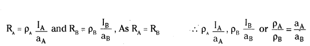
The radius of conducting wire is doubled. What will be the ratio of its new specific resistance to the old one ?
Answer:
1 : 1, as it depends on the nature of material only.
Question 6.
Why is magnanin used for making standard resistors ?
Answer:
Magnanin being an alloy has a low temperature coefficient of resistance.
Question 7.
Write the S.I. unit of resistivity.
Answer:
Ohm-metre.
Question 8.
How will the resistivity of a conductor change when its length is tripled by stretching it?
Answer:
The resistivity of a metallic conductor does not depend on the length of the wire, so it will remain same.
Question 9.
Why is closed path required for the flow of current ?
Answer:
It makes possible to move the electrons in a particular direction. So closed path is necessary for the flow of current.
Question 10.
A lamp draws a current of 0.5 A when it is connected to a 60 V source. What is the resistance of the lamp ?
Answer:
From Ohm’s law, I = VR we get,
R = VI = 600.5 = 120 Ω
Question 11.
A torch bulb is rated at 1.5 V, 500 m
Answer: Find its resistance.
Answer:
From Ohm’s law, I = VR we get,
R = VR = 1.5500 × 10-3 = 3 n
Question 12.
How is an ammeter connected in a circuit to measure current flowing through it ?
Answer:
It is always connected in series in a circuit through which the current is to be measured.
Question 13.
Which combination is used for connecting the device in the circuit to measure the potential difference across two points ?
Answer:
Parallel combination.
Question 14.
How are bulbs connected in a fairy light circuit used for decoration of buildings in festivals ?
Answer:
Series combination.
Question 15.
Why do we not prefer series connection at home ?
Answer:
Even if one device is damaged, all the devices will stop functioning.
Question 16.
two bulbs 60 W, 220 V and 40 W, 220 V are connected in series. Which of the bulb will glow brighter ?
Answer:
More power is dissipated by 40 W bulb as it has a higher resistance. So, it will glow brighter in series.
Question 17.
Name the element of filament of a bulb.
Answer:
Tungsten.
Question 18.
Name the device used to safeguard electrical devices at home.
Answer:
Fuse wire.
Question 19.
Write relation between heat energy produced in a conductor, when a potential difference V is applied across its terminals and a current I flows through for ‘t’.
Answer:
Heat produced H = VIt.
Question 20.
There are two electric bulbs OD marked 60 W, 220 V and (ii) marked 100 W, 220 V. Which one of the two has a higher resistance ?
Answer:
P = V2R ⇒ P ∝ 1 R ⇒ R ∝ 1 P
Question 21.
A uniform wire of resistance 20 Ω is cut into two equal parts. These parts are how connected in parallel. What will be the resistance of the combination ?
Answer:
∵ R ∝ l
∴ ResIstance of each part is 10 Ω ∴ Req = 10×1010+10 = 10020 = 5Ω
Question 22.
List any two factors on which resistance of a conductor depends.
Answer:
Length and area of cross-section.
Question 23.
a) Name the device used to measure electric current in a circuit.
b) How is an ammeter connected in a circuit to measure current flowing through it?
Answer:
a) Ammeter
b) In series
Question 24.
In an electric circuit, state the relationship between the direction of conventional current and the direction of flow of electrons.
Answer:
The direction of conventional current is opposite to the direction of flow of electrons.
Question 25.
How does the resistivity of alloys compare with those of pure metals from which they may have been formed ?
Answer:
Alloys have higher resistivity in comparison to pure metals.
Question 26.
Write the SI unit of resistivity.
Answer:
Ohm - metre (Ωm).
Question 27.
Power of a lamp is 60 W. Find the energy in Joules consumed by it in 1s.
Answer:
Energy consumed = p × t = 60 × 1 = 60 J.
Question 28.
What is the SI unit of electric potential ?
Answer:
In SI, electric potential is measured in volt (V).
Question 29.
Write the mathematical expression for electric potential.
Answer:
Mathematically, electric potential is written as V = WQ.
Question 30.
Is electric potential a scalar quantity or a vector quantity ?
Answer:
It is a scalar quantity.
Question 31.
How can we maintain a potential difference across a conductor ?
Answer:
By using a source of emf. For example a battery.
Question 32.
Give a single word for 1 Joule 1 Coulomb .
Answer:
1 Volt.
Question 33.
How many Joule are there in one kilowatt hour ?
Answer:
3.6 × 10⁶ J.
Question 34.
How does the resistance of a wire vary with its cross-sectional area ?
Answer:
It varies inversely with the cross-sectional are.
Question 35.
Define current. Give its SI unit.
Answer:
Current is defined as the rate of flow of electrons. It is measured in ampere (A).
Question 36.
State Ohm’s law.
Answer:
Physical conditions remaining same, the electric current flowing through a conductor is directly proportional to the potential difference across the two ends of the conductor.
Question 37.
What is meant by resistance ?
Answer:
It is the opposition offered to the flow of electrons by a conductor.
Question 38.
What are the units of resistance ?
Answer:
It is measured in Ohm.
Question 39.
What is meant by 1 ohm resistance ?
Answer:
The resistance of a conductor is said to be 1 ohm if under a potential difference of 1 volt a current of one ampere flows through the conductor.
Question 40.
What will happen to the current flowing through a conductor, if the potential difference is doubled ?
Answer:
The current is also doubled.
Question 41.
What is meant by equivalent resistance ?
Answer:
It is the combination of number of resistances.
Question 42.
When do we say that the resistors are connected in series ?
Answer:
When the current through each resistor is same.
Question 43.
When do we say that the resistors are connected in parallel ?
Answer:
When the potential difference across each resistor is same.
Question 44.
What are the factors on which resistivity of a material depends ?
Answer:
It depends only upon the nature of the conductor.
Question 45.
What will happen to the current in a circuit, if the current through it is doubled ?
Answer:
No change, since resistance does not depend upon current.
Question 46.
Define electric power. Give its S.I. unit.
Answer:
The rate of work, or the rate of dissipation of energy is called electric power. It is measured in watt (W).
Question 47.
What is the commercial unit of electric energy ?
Answer:
Kilo Watt - Hour (KWH)
Question 48.
Give two practical applications of heating effect of current.
Answer:
Electric Geyser and Electric Iron.
Question 49.
Why should the melting point of a fuse wire below ?
Answer:
It melts as soon as the safe limit of current is exceeded.
Question 50.
Write the Joule’s law of heating.
Answer:
H = I2 Rt.
Question 51.
Define one watt hour.
Answer:
It is defined as the energy consumed by an agent of power 1 watt in one hour.
1 watt hour = 1 watt × 1 hour
= (1 Js-1) × 3600 s = 3600 J.
Question 52.
A cylinder of a material is 10 cm long and has a cross-section of 2 cm2. If its resistance along the length be 20 ohm, what will be its resistivity in number and units ?
Answer:
We know that ρ = RA L = 20×210 = 4 ohm cm.
Question 53.
State which has a higher resistance a 50 W or a 25 W lamp bulb and how many times ?
Answer:
We know that R = V2P or R ∝ 1P
Thus, a 25 W lamp has double the resistance of a 50 W lamp.
Question 54.
Out of two, a toaster of 1 KW and an electric heater of 2 KW, which has a greater resistance ?
Answer:
We know that R = v2ρ or R ∝ 1P
Thus, the 1 KW toaster, has more resistance than a 2 KW electric heater.
Question 55.
What is the resistance of an electric arc lamp, if the lamp uses 20 A when connected to 220 V line ?
Answer:
R = Vt = 22020 = 11 ohm.
Question 56.
Does an ammeter have a low or a high resistance ?
Answer:
An ammeter has a low resistance.
Question 57.
What is the resistance of an ideal ammeter ?
Answer:
An ideal ammeter has zero resistance.
Question 58.
What is the resistance of an ideal voltmeter ?
Answer:
An ideal voltmeter has infinite resistance.
Question 59.
What is lowest resistance that can be obtained by combining four coils of resistance 4 Ω,8 Ω, 12 Ω and 24 Ω?
Answer:
By combining them in parallel. The lowest resistance which can be obtained is 2 Ω.
Question 60.
Give an example of a metal, which is the best conductor of heat.
Answer:
Silver or copper.
Question 61.
What happens to the resistance of a conductor when temperature is increased ?
Answer:
Its resistance increases.
Question 62.
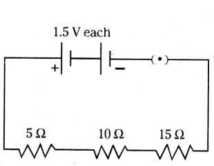
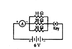
Draw a schematic diagram of a circuit consisting of a battery of two cells each of 1.5 V, 5 Ω, 10 Ω, and 15 Ω resistors and a plug key, all connected in series.
Answer:
The diagram is as shown below.
Question 63.
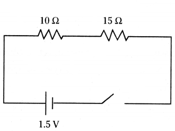
Draw a schematic diagram of a circuit consisting of a cell of 1.5 V, 10 Ω resistor and 15 Ω resistors and a plug key, all connected in series.
Answer:
The diagram is as shown below.
Question 64.
Observe the experimental set up carefully.
You are provided with four types of metallic wires i.e., silver wire, copper wire, lead wire and iron wire. Which type of metallic wire would you like to put in the circuit between gap of two terminals A and B, so that circuit show maximum conductivity.
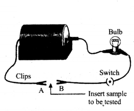
Answer:
Silver type of metallic wire.
Question 65.
In which of the circuits below does a current exist to light the bulb ?
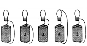
Answer:
In circuit 5.
Question 66.
While performing the experiment of Ohm’s law, a student has plotted the following graph. What will be the resistance of the conductor ?
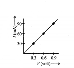
Answer:
10 W
Question 67.
Two LED bulbs of 12W and 6W are connected in series. If the current through 12W bulb is 0.06A.What will be the current through 6W bulb ?
Answer:
0.06 A
Question 68.
Two bulbs of 100 W and 40 W are connected in series. The current through the 100W bulb is 1
Answer: What will be the current through the 40 W bulb ?
Answer:
1A
Question 69.
Assertion (A) : The metals and alloys are good conductors of electricity.
Reason (R) : Bronze is an alloy of copper and tin and it is not a good conductor of electricity.
a) Both (A) and (R) are true and (R) is the correct explanation of the assertion (A).
b) Both (A) and (R) are true, but (R) is not the correct explanation of the assertion (A).
c) (A) is true, but (R) is false. d) (A) is false but (R) is true.
Answer:
c) (A) is true, but (R) is false.
Question 70.
Assertion (A) : Alloys are commonly used in electrical heating devices like electric iron and heater.
Reason (R) : Resistivity of an alloy is generally higher than that of its constituent metals but the alloys have low melting points then their constituent metals.
a) Both (A) and (R) are true and (R) is the correct explanation of the assertion (A).
b) Both (A) and (R) are true, but (R) is not the correct explanation of the assertion (A).
c) (A) is true, but (R) is false.
d) (A) is false but (R) is true.
Answer:
c) (A) is true, but (R) is false.
Question 71.
A cell of e.m.f 2V and internal resistance 0.1 Ω is connected to a 3.9 Ω external resistance. What will be the p.d. across the terminals of the cell ?
Answer:
V = E - Ir = 2 - I × 0.1
Also = ER+r = 23.9+0.1 = 24 = 12 = 0.5A
∴ V = 2 - 0.5 × 0.1 = 2 - 0.05 = 1.95 V
Question 72.
Six equal resistors of 1 Ω each are connected to form a hexagon ABCDEF as shown. If the current enters at A and leaves at D, find the resistance offered by the combination.
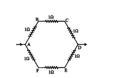
Answer:
1R = 13 + 13 ⇒ R = 32 = 1.5 Ω
Electricity Class 10 Important Questions - 2 Marks
Question 1.
List in a tabular form two differences between a voltmeter and an ammeter.
Answer:
| Voltmeter |
Ammeter |
| a) Used to measure potential difference. |
a) Used to measure current. |
| b) Connected in an electric circuit. |
b) Connected in series in the electric circuit. |
| c) Has high resistance. |
c) Has low resistance. |
Question 2.
State the factors on which the heat produced in a current carrying conductor depends. Give one practical application of this effect.
Answer:
i) Heat produced in a current carrying conductor depends upon :
a) Square of the current (I2).
b) Resistance of the given conductor (R).
c) Time for which the current flows (t).
ii) This effect is applicable in electric heating device like electric iron.
Question 3.
Elements of electric toasters and electric iron are made of an alloy rather than a pure metal. Give two reasons to justify the statement.
Answer:
a) Alloys do not oxidise readily at high temperature, so they are more resistant to corrosion.
b) Alloys have lower electrical conductivity than pure metals.
Question 4.
Give reason for the following :
i) Tungsten used almost exclusively for filament of electric lamp.
ii) Why do we use copper and aluminium wires for transmission of electric current?
Answer:
i) Tungsten is used in making the filament of an electric bulb because :
a) Tungsten has high melting point.
b) Tungsten has high resistivity to retain much heat.
ii) Copper and aluminium have low resistivity and they are good conductors of electricity, so, they are used for transmission of electric current.
Question 5.
Explain the terms potential and potential difference. Give their Si units.
Answer:
Potential : Potential at a point is defined as the amount of work done in moving a unit charge from infinity to that point.
Potential difference : Potential difference between two points is defined as the amount of work done in moving a unit charge between the two points.
Both potential and potential difference are measured in volt.
Question 6.
If you connect three resistors having values 2 ohm, 3 ohm and 5 ohm in parallel, will the value of total resistance be less than 2 ohm or greater than 5 ohm or lie between 2 ohm and 5 ohm ? Explain.
Answer:
The value of the equivalent resistance will be smaller than the least value of resistance in the combination. Thus, the total resistance will be less than 2 ohm. This can be found as follows
1R = 12 + 13 + 15 = 15+10+630 = 3130
or R = 3031 = 0.967 ohm.
Question 7.
How would the reading of voltmeter (V) change, if it is connected between B and C ? Justify your answer.
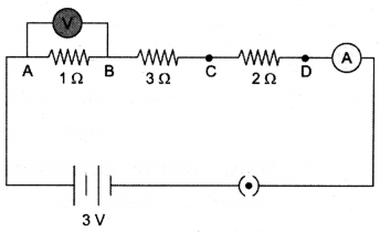
Answer:
R = R1 + R2 + R3 = 1 + 2 + 3 = 6 Ω
V = IR
I = VR = 36 = 12A
Voltage across 1Ω, V = IR = 12 × 1 = 0.5 V
Voltage across 3Ω, V = IR = 12 × 3 = 1.5 V.
Question 8.
a) List the factors on which the resistance of a conductor in the shape of a wire depends.
b) Why are metals good conductors of electricity whereas glass is a bad conductor of electricity ? Give reason.
c) Why are alloys commonly used in electrical heating devices ? Give reason.
Answer:
a) i) Length of the conductor.
ii) Area of cross-section of the conductor.
iii) Nature of the material of the wire.
b) Metals have free electrons which make conduction of electricity easy, while glass does not have free electrons.
c) Because they have high resistivity and high melting point.
Question 9.
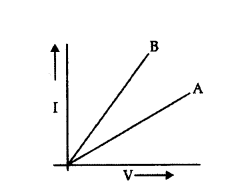
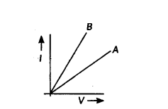
V-I graphs for two wires A and B are shown in the figure.
If both the wires are made of the same material and are of equal thickness, which of the two is of more length? Give justification for your answer.
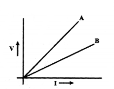
Answer:
We know that V = IR
For the same current wire A requires more.
Voltage, hence resistance of A is more than that of B, R = ρl A.
Since ρ and A are same for both wires and R, l.
∴ Length of A is more than that of B.
Question 10.
Find the number of electrons transferred between two points kept at a potential difference of 20 V if 40 J of work is done.
Answer:
Here, potential difference (V) = 20 V; Work (W) = 40 J
We know that
Work (W) = Charge (Q) × Potential difference (V)
or 40 J = Q × 20 V
or = 40 J20 V = 2C
Number of electrons = 2C1.6×10?19C = 1.25 × 10¹⁹
Question 11.
A nichrome wire has a resistance of 10 Ω. Find the resistance of another nichrome wire, whose length is three times and area of cross-section four times the first wire.
Answer:
Resistance (R) of first wire = ρl A
Resistance (R1) of second wire = ρ×3l4 A = 3ρl4 A
So the resistance of the second wire is three-fourth the resistance of the first wire i.e. 7.5 Ω.
Question 12.
A hot plate of an electric oven connected to a 220 V line has two resistors A and B each of 22 Ω resistance. These resistors may be used separately, in series or in parallel. Find the current flowing in all the three cases.
Answer:
a) Separately : Current I = VR = 22022 = 10 A
b) In series : R = R1 + R2 = 22 + 22 = 44 Ω
∴ I = VR = 22044 = 5A
c) In Parallel : 1R = 1R1 + 1R2 = 122 + 122 = 111
∴ R = 11 Ω
I = VR = 12 = 20A
Question 13.
Calculate the potential difference between the two terminals of a battery if 100 Joules of work is required to transfer 20 coulombs of charge from one terminal of the battery to the other.
Answer:
The relation is V = WQ
Given W = 100J.Q = 20 ; V = ?
Using the relation V = WQ
we have V = 10020 = 5 V
Question 14.
Calculate the current in a circuit if 500 C of charge passes through it in 10 minutes.
Answer:
a) The direction of electric current is opposite to the direction of flow of electrons in a wire.
b) Given Q = 500 C ; t = 10 minutes = 10 × 60 = 600 S ; I = ?
Using relation = Qt = 500600 = 0.83 A
Question 15.
a) What is the total resistance of n resistors each of resistance ‘R’ connected in (i) series 00 parallel ?
b) Calculate the resultant resistance of 3 resistors 3 Ω, 4 Ω and 12 Ω connected in parallel.
Answer:
a) In series combination, we have Rs = R1 + R2 + ... to n = nR
In parallel combination, we have 1Rp = 1R1 + 1R2 + ..... n
or Rp = Rn
b) In parallel, we have 1Rp = 1R1 + 1R2 + 1R3 = 13 + 14 + 112 (or) Rp = 128 = 1.5 Ω.
Question 16.
What are the factors on which heat dissipated by a conductor depends ?
Answer:
Heat dissipated depends upon :
i) the square of current through the conductor
ii) the resistance of the conductor and
iii) the time for which current is passed.
Question 17.
Why is heat produced when a current is passed through a conductor ?
Answer:
During their motibn, the electrons collide with one another and hence lose some kinetic energy. This loss in kinetic energy is dissipated as heat across the conductor.
Question 18.
An electric iron of resistance 20 Ω takes a current of 5A. Calculate the heat developed in 30s.
Answer:
Here, I = 5A, R = 20 Ω, t = 30s
Heat developed = I2Rt
= 52 × 20 × 30 J
= 15000 J.
Question 19.
The following table gives the value of electrical resistivity of some materials.
| Material |
Copper |
Silver |
Constantan |
| Electrical resistivity (Ωm) |
1.62 × 10⁻⁸ |
1.6 × 10⁻⁸ |
49 × 10-4 |
Which one is the best conductor of electricity out of them ?
Answer:
Silver is the best conductor of electricity because it has the least resistivity value.
Question 20.
What is an electric circuit ? Distinguish between an open and a closed circuit.
Answer:
- A closed and continuous path along which an electric current flows is called an electric circuit.
- An electric circuit through which no current flows is called an open circuit.
- An electric circuit through which current flows continuously is called closed circuit.
Question 21.
How is electric current expressed, and what is the unit of small quantities of current?
Answer:
- Electric current is expressed as the rate of flow of electric charges.
- The unit of felectric current is the ampere (A).
- Small quantifies of current are expressed in milliampere (mA, 10-3 A) or microampere (?A, 10-6 A).
Question 22.
What is the potential difference across a resistor if the current through it is 5 A and the resistance is 4 Ω ?
Answer:
- The potential difference across a resistor can be calculated using Ohm’s law, which states that V = I × R.
- Here, V is the potential difference, 1 is the current, and R is the resistance.
- In this case, the current through the resistor is given as 5 A and the resistance is 4 Ω.
- Plugging these values into Ohm’s law, we get V = 5 A × 4 Ω, which simplifies to V = 20 V. Therefore, the potential difference across the resistor is 20 volts.
Question 23.
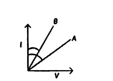
Two V - I graphs A and B for series and parallel combinations of two resistors are as shown. Giving reason state which graph shows (a) series, (b) parallel combination of the resistors.
Answer:
As Rseries > Rparallel
⇒ (slope)series > (Slope)parallel
[∵ R = slope of i - v curve]
As ‘A’ has less slope than ‘B’, so ‘A’ is parallel combination and ‘B’ is series combination.
Question 24.
A student has two resistors 2 Ω and 3 Ω. She has to put one of them in place of R2 as shown in the circuit. The current that she needs in the entire circuit is exactly 9A. Show by calculation which of the two resistors she should choose.
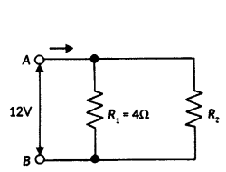
Answer:
The overall current needed = 9A. The voltage is 12V.
Hence by Ohm’s Law V = IR,
The resistance for the entire circuit = 129 = 43Ω = RR1 and R2 are in parallel.
Hence R = R1R2R1+R2 = 4R 24+R2 = 43R2 = 2 Ω
Question 25.
Let the resistance of an electrical device remain constant, while the potential difference across its two ends decreases to one fourth of its initial value. What change will occur in the current through it ? State the law which helps us in solving the above stated question.
Answer:
- As R is constant, so by Ohm’s law current through the conductor is directly proportional to potential difference across it.
- Therefore if potential difference is decreased to one-fourth of initial value, current will also decrease to one-fourth of initial value.
Question 26.
Priya has a copper wire and aluminium wire of the same length.
Can you electrical resistance of the two wires be the same ? Justify your answer.
Answer:
Yes, the electrical resistance of the two wire can be the same.
Reason :
i) If the area of cross - section of the two wire is same, (or)
ii) If the thickness of the two wires is different.
Question 27.
A V-I graph for a nichrome wire is given below.
What do you infer from this graph? Draw a labelled circuit diagram to obtain such a graph.

Answer:
The graph shows that potential difference is directly
proportional to current I.e., V ∝ I.
Circuit diagram to obtain the graph.
Question 28.
The current flowing through a resistor connected in circuit and the potential difference developed across its ends are as shown in the diagram by milliammeter and voltmeter readings respectively :
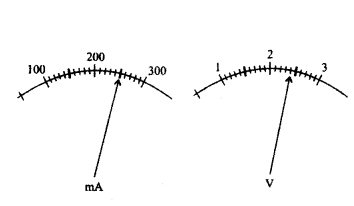
a) What are the least counts of these meters ?
b) What is the resistance of the resistor ?
Answer:
a) Least counts of meters are 10 mA and 0.1 V.
b) Given,
Voltage, V = 2.4 Volt, Current , I = 250 mA
Using Ohm’s law: V = IR
⇒ R = VI = 2.4 V250 mA ⇒ R = 2.4 V0.25 A = 9.6 Ω
Question 29.
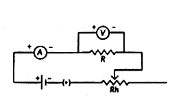
While studying the dependence of potential difference (V) across a resistor on the current 0) passing through it, in order to determine the resistance of the resistor, a student took 5 readings for different values of current and plotted a graph between V and I. He got a straight line graph passing through the origin. What does the straight line signify ? Write the method of determining resistance of the resistor using this graph.
Answer:
The straight line obtained verifies Ohm’s law.
Slope of the graph = ∆I∆R = 1R
⇒ R = 1 Slope of the graph = ∆V∆I
In this way, resistance can be determined.
Question 30.
The resistance of a wire of 0.01cm radius is 10 Ω. If the resistivity of the material of the wire is 50 × 10-8 ohm meter, find the length of the wire.
Answer:
Given, Radius (r) = 0.01 cm = 0.01 × 10⁻² m
Resistivity (r) = 50 × 10-8 Ωm.; Resistance (R)= 10 Ω
As we know, [∵ A = πr2]
R = ρl A = lπr2 ⇒ l = Rπr2ρ = 10×3.14×0.01×10?2×0.01×10?250×10?8 = 314×10?450×10?8×10⁵
∴ Length = 6.28×10?410?3 = 0.628 m
Question 31.
A piece of wire of resistance R is cut into three equal parts. These parts are then connected in parallel. If the equivalent resistance of this parallel combination is R1 what is the value of the ratio R1 : R ?
Answer:
Resistance of each part is R3 Ω
(as resistance is proportional to the length of the wire)
1R1 = 3R + 3R + 3R = 9R
∴ R1 = R9 ∴ R1R = 19
Question 32.
If the equivalent resistance of the arrangements (I) and (II) are Rs and Rp respectively, then which one of the following V - 1 graphs is correctly labelled ? Justify your answer.
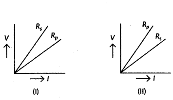
Answer:
We know that the slope of V-I graph gives the resistance.
The greater the slope, greater will be the resistance.
The greater the slope, greater will be the resistance. From figure, Rs > Rp so graph (i) is correct.
Question 33.
Calculate the resistance of a metal wire of length 2 m and area of cross section 1.55 × 10⁻⁶ m2. (Resistivity of the metal is 2.8 × 10⁻⁸ Ωm)
Answer:
Here, the length of the wire, l = 2 m; Area of cross-section, A = 1.55 × 10⁻⁶m2
Resistivity of metal, ρ = 2.8 × 10⁻⁸ Ωm
Formula of resistance, R = ρlA
∴ R = 2.8×10?8×21.55×10?6 = 3.61 × 10⁻²Ω
Question 34.
A student boils water in an electric kettle for 20 minutes. Using the same main supply he wants to reduce the boiling time of water. To do so should he increase or decrease the length of the heating element ? Justify your answer
Answer:
- To reduce the boiling time using the same mains supply, the rate of heat production should be large.
- We know that P = V2R.
- Since V is constant, R should be decreased.
- Since R is directly proportional to I so length should be decreased.
Question 35.
How will the resistance of a wire be affected if its
1. Length is doubled, and
2. radius is also doubled.
Give justification for your answer.
Answer:
1) As R ∝ l
So if length is doubled, then resistance also get doubled.
2) As R ∝ l A i.e., R ∝ lr2 [∵ A = r2]
So if radius is doubled, then resistance becomes one-fourth.
Question 36.
Calculate the equivalent resistance of the following network.
Answer:
In the given circuit, two resistors of 20 Ω connected in parallel. So, their equivalent resistance is
1R = 120Ω + 120Ω = 110Ω ⇒ R = 10 Ω
This combination is in series with a resistor of 10 Ω.
Net equivalent resistance, R’ = R + 10 Ω = 10 Ω + 10 Ω = 20 Ω
Question 37.
How is electric current related to the potential difference across the terminals of a conductor ? Draw the labelled circuit diagram to verify this relationship.
Answer:
It states that the potential difference V, across the ends of a given metallic wire in an electric circuit is directly proportional to the current flowing through it, provided its temperature remains the same. Mathematically
V ∝ I; V = RI
Question 38.
Two V-l graphs A and B for series and parallel combinations of two resistors are as shown. Giving reason state which graph show (a) series, (b) parallel combination of the resistors.
Answer:
R5 = R1 + R2 = Maximum resistance
RP = R1R2R1+R2 = minimum resistance
So, RA > RB
Question 39.
A 6 Ω resistance wire is doubled on itself. Calculate the new resistance of the wire.
Answer:
Given resistance of wire, R = 6 Ω
Let / be the length of the wire and A be its area of cross-section. Then R = ρl A = 6 Ω
Now when the length is doubled, l’ = 21 and A’ = A2
∴ R’ = ρ(2l)A2 = 4ρlA = 4 × 6 Ω = 24 Ω
Question 40.
Three 2 Ω resistors A, B and C are connected in such a way that the total resistance of the combination is 3 Ω. Show the arrangement of the three resistors and justify your answer.
Answer:
The total resistance of the combination = 3 Ω
So we can combine the two resistors in parallel.
Therefore the three resistors will be connected as follows.
Such that 1RP = 12 + 12 = 1 ⇒ RP = 1 Ω
RS = 2 Ω + 1 Ω = 3 Ω
Important Questions on Electricity Class 10 - 4 Marks
Question 1.
Write symbols used in electric circuits to represent
a) i) variable resistance
ii) voltmeter
b) An electric bulb is rated 220 V and 100 W. When it is operated on 110 V. What will be the power consumed ?
Answer:
a) i) Variable resistance 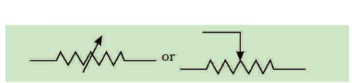
ii) Voltmeter 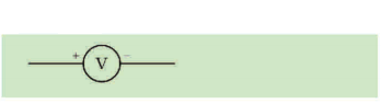
b) Given, P = 100 W, V = 220 V; V1 = 110 V
The resistance of the bulb is given by R = V2P = (220)2100 = 48 Ω
Now, power at 110 V is P = V2R = (110)2100= 25 W.
Question 2.
Two conducting wires of same material, equal length and equal diameter are connected in series. How does the heat produced by the combination of resistance change ?
Answer:
Let the resistance of the wire be R.
When connected in series,
The total resistance is R = R + R = 2R
Heat produced by series combination H = V22R t
Heat produced by individual resistors H’ = V2R t
∴ H’ = H2
Question 3.
Study the following circuit and answer the questions that follow.

a) state the type of the combination of two resistors in the circuit.
b) How much current is flowing through
i) 10 Ω and through
ii) 15 Ω resistors ?
c) What is ammeter reading ?
Answer:
Here V = 3V, R1 = 10 Ω, R2 = 15 Ω
a) The two resistors are connected in a parallel combination.
b) i) Current through 10 Ω resistor I1 = VR1 = 3 V10Ω = 0.3 A
ii) Current through 15 Ω resistor I2 = VR2 = 3 V15Ω = 0.2 A
c) Ammeter reading I = I1 + I2 = 0.3 + 0.2 = 0.5 A
Question 4.
Resistivity of two elements A and Bare 1.62 × 10⁻⁸ Ωm and 520 × 10-8 Ωm respectively Out of these two, name the element that can be used to make
i) Filament of electric bulb
ii) Wires for electrical transmission lines. Justify your answer in each case.
Answer:
i) Element B: It has more resistivity (520 × 10-8 Ωm)
ii) Element A : It has less resistivity and hence less heating effect / dissipation of energy during transmission of power.
Question 5.
Find out the reading of ammeter and voltmeter in the circuit given below.
Answer:
Equivalent resistance of given series combination
Rs = R1 + R2 + R3 + R4 = 2 + 3 + 3 + 4 = 12 Ω
i) Ammeter reading I = VR = 612 = 0.5 A
ii) Voltmeter reading V = IR = 0.5 × 2 = IV.
Question 6.
Define 1 Volt. Express it in terms of SI unit of work and charge. Calculate the amount of energy consumed in carrying a charge of 1 coulomb through a battery of 3 V.
Answer:
When I Joule of work is done in carrying 1 coulomb of charge, from infinity to a point in the
Potential difference between two points is V = WQ
or W = Q × V = 1 × 3 = 3 J
electric field then potential at that point is called 1 volt.
Question 7.
Find the equivalent resistance across the two ends A and B of the following circuit.
Answer:
All five resistance are connected in series.
Therefore, their equivalent resistance is
Req = R1 + R2 + R3 + R4 + R5
= R + R + R + R + R
= 5 R.
Question 8.
Find the equivalent resistance across the two ends A and B of the following circuit.
Answer:
R2 and R3 are in series, So Rs = R2 + R3 = 5 + 5 = 10 Ω
R1, Rs, R4 are in parallel, So 1Rp = 1R1 + 1Rs + 1R4 = 15 + 110 + 15
⇒ 1Rp = 510 or Rp = 2 Ω.
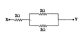
Question 9.
Out of the two wires X and Y shown below, which one has greater resistance ? Justify your answer.
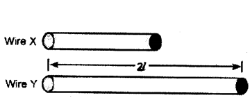
Answer:
Wire ‘Y’ has greater resistance as it has more length than wire ‘X’. It is because resistance of wire is directly proportional to the length of wire for the same area of cross-section for the same material.
Question 10.
A given length of a wire is doubled on itself and this process is repeated once again. By what factor does the resistance of the wire change ?
Answer:
Length becomes one-fourth of the original length and area of cross-section becomes four times that of original.
i.e., l2 = 14l1 and A2 = 4A
∴ R2R1 = l2l1 × A1 A2 = 14 × 14 = 116
⇒ R2 = 116R1
So, new resistance is (116)th of original resistance.
Question 11.
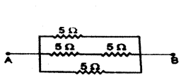
Find the equivalent resistance between the points A and B.
Answer:
i) Points P and Q are at the same potential. The resistance 5 Ω. between P and Q is ineffective
∴ RAB = 5 Ω, + 5 Ω, = 10 Ω
ii) Point Q has the same potential as the point A and point P has the same potential as
the point B. So, the three resistances are connected in parallel between A and B.
1RAB = 15 + 15 +15 = 35
∴ RAB = 53 Ω.
Question 12.
Find the current drawn from the battery by the network of four resistors shown in the figure.
Answer:
The combinations (10 Ω + 10 Ω) and (10 Ω + 10 Ω) are connected in parallel
Req = 20×2020+20 = 10 Ω
Current drawn from the battery is I = VReq = 3 V10Ω = 0.3 A
Question 13.
Four resistances of 2 Ω each are joined to form a square ABCD. Calculate the equivalent resistance of the combination between any two adjacent corners.
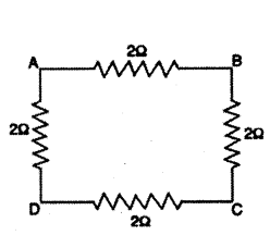
Answer:
The arrangement of four resistances is shown below
RAB = 2Ω
RADCB = 2Ω + 2Ω + 2Ω = 6Ω
These two resistances are connected in parallel. The equivalent resistance R between A and B is given by
1P = 1RAB + 1RADCB = 12 + 16 + 46
∴ R = 1.5Ω
Question 14.
For the combination of resistors shown in the adjacent figure, find the equivalent resistance between M and N.
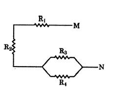
Answer:
The parallel combination of R3 and R4 is connected in series with R1 and R2
∴ RMN = R1 + 2 = R3R4R3+R4.
Question 15.
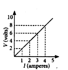
In the experiment to study the dependence of current (I) on the potential difference (V) across a resistor, a student obtained a graph as shown.
i) What does the graph depict about the dependence of current of the potential difference ?
ii) Find the current that flows through the resistor when the potential difference across it is 2.5 V.
Answer:
i) As the graph between V and I is linear. So, V ∝ I
ii) From the given graph, when V = 2.5 V, I = 0.25 A.
Question 16.
List the factors on which the resistance of a conductor in the shape of a wire depends. Write the formula showing relation of resistance with these factors.
Answer:
Factors affecting the resistance : At a constant temperature, the resistance of a conductor depends on the following factors.
1) Length : Resistance R of a conductor is directly proportional to its length L.
i.e., R ∝ L
2) Area of cross-section : Resistance R of conductor is inversely proportional to its area of cross-section A.
i.e., R ∝ 1 A
3) Nature of the material : Resistance also depends on the nature of the material of which the conductor is made. The resistance of a copper wire is much less than that of a nichrome wire of same length and area of cross-section.
Combining the above factors, we get, R ∝ LA ⇒ R = ρLA
The proportionality constant ρ is called resistivity or specific resistance which depends on the nature of the material.
Question 17.
a) Define electrical resistivity of a material.
b) Write the relation between resistance and electrical resistivity of the material of a conductor in the shape of a cylinder of length ‘L’ and area of cross-section ‘A’. Hence derive the SI unit of electrical resistivity.
Answer:
a) Resistivity : If in the equation R = ρ LA
We take, L = 1m and A = 1 m2
R = ρ
then resistivity is defined as the resistance offered by a cube of a material of side 1 m, when current flows perpendicular to its opposite faces.
b) S.I. Unit of resistivity is ohm metre :
We have ρ = R×AL
∴ SI unit of resistivity = ohm × metre 2 metre = ohm metre (Ωm).
Question 18.
Show four different ways in which three resistors of ‘r’ ohm each may be connected in a circuit. In which case is the equivalent resistance of the combination
i) maximum ?
ii) minimum ?
Answer:
The four different ways of connecting three resistances and their equivalent resistance are shown below.
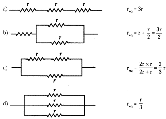
i) Equivalent resistance is maximum for series combination (a)
ii) Equivalent resistance is minimum for parallel combination (d).
Question 19.
Two resistors X and Y or resistances 2Ω and 3Ω respectively are first joined in parallel and then in series. In each case the voltage supplied is 5 V.
a) Draw circuit diagrams to show the combination of resistors in each case.
b) Calculate the voltage across the 3 resistor in the series combination of resistors.
Answer:
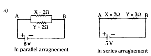
b) Rs = 2Ω + 3Ω = 5 Ω
I = VRs = 5 V5Ω = 1A
Voltage across 3Ω resistor,
V = IRy = 1 × 3 = 3V
Question 20.
Draw a schematic diagram of a circuit consisting of a battery of 3 cells of 2 V each, a combination of three resistors of 10 Ω, 20 Ω and 30 Ω connected in parallel, a plug key and an ammeter, all connected in series.
Use this circuit to find the value of the following :
a) Current through each resistor
b) Total current in the circuit
c) Total effective resistance of the circuit
Answer:
The circuit diagram is shown below.
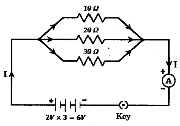
a) Current through 10 Ω resistor
I1 = VR1 = 6 V10Ω = 0.6 A
Current through 20 Ω resistor
I2 = VR2 = 6 V20Ω = 0.3 A
Current through 30 Ω resistor I3 = VR1 = 6 V30Ω = 0.2 A
b) Total current in the circuit 1 = I1 + I2 + I3 = 0.6 + 0.3 + 0.2 = 1.1 A
c) Total effective resistance R is given by
1R = 1R1 + 1R2 + 1R3
110 + 120 + 130 = 1160
Or R = 6011Ω = 5.45 Ω.
Question 21.
Define the term electric power. Write an expression for it.
Answer:
Electric power : The electric power of an appliance is the rate at which it consumes electrical energy or it is defined as the rate at which work is done in maintaining an electric current in an electric circuit.
When a current I flows through a circuit for a time t at a constant potential difference V, then the work done is, W = VIt Joule
∴ Electric power P = Wt = VItt
p = VI = I2R = V2R
Electric power = voltage × current.
Question 22.
Calculate the following from the electric circuit given in figure.
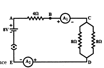
a) Effective resistance of the combination of two 8 Ω resistors
b) Current flowing through 4 Ω resistor
c) Potential difference across 4 Ω resistance
d) Power dissipated in 4 Ω resistor
e) Difference in ammeter readings, if any.
Answer:
a) The two 8 Ω resistors are connected in parallel between C and D. Their effective resistance is
R’ = 8×88+8 = 4Ω
b) Total resistance in the circuit R = 4Ω + R’ = 4Ω + 4Ω = 8Ω
Current I = VR = 8 V8Ω = 1A
∴ Current through the 4Ω resistor = 1A
c) Potential Difference (P.D.) across 4 Ω resistor V = IR = 1 × 4 = 4V
d) Power dissipated in 4 Ω resistor P = I2R = (1)2 × 4 = 4 W
e) As both the ammeters A1 and A2 are connected in series in the circuit, there will be no difference in their readings.
Question 23.
Two identical resistors, each of resistance 15 Ω, are connected in (i) series and (ii) parallel, in turn to a battery of 6 V. Calculate the ratio of the power consumed in the combination of resistors in each case.
Answer:
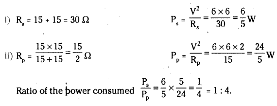
Question 24.
How much current will an electric bulb draw from 220 V source, if the resistance of the bulb is 1 200 Ω ? If in place of bulb, a heater of resistance 100 Ω is connected to the source, calculate the current drawn by it.
Answer:
Given V = 220 V; R1 = 1200 Ω, I1 = ?
R2 = 100 Ω, I2 = ?
Using ohm’s law, V = I1 R1
⇒ I1 = VR1 = 2201200 = 0.18 A
and I2 = VR2 = 220100 = 2.2 A
Question 25.
100 J of work is done in transferring 20 C of charge between two points in a conductor. Find the resistance offered by the conductor, if a current of 2A flows through it.
Answer:
Given W = 100 J, q = 20 C, I = 2A, R = ?
Work done in carrying 20 C charge W = QV
From ohm’s law V = IR
W = q (IR)
⇒ R = WQI = 10020×2 = 52
R = 2.5Ω
Question 26.
In the above circuit, if the current reading in the ammeter A is 2A, what would be the value of R1 ?
Answer:
5 ohm, 10 ohm and R1 are in parallel
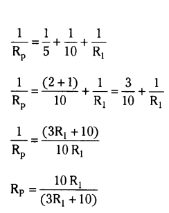
Now, 6 ohm, 6 ohm and Rp are in series
Thus,
Req = 12+10R1(3R1+10) _______ (1)
V = I Req
From the circuit
Req = 302 = 15 Ω _______ (2)
Equating (1) and (2)
12+10R1(3R1+10) = 15
10R1(3R1+10) = 3
10 R1 = 9 R1 + 30
Thus, R1 = 30 ohm.
Question 27.
Calculate the total resistance of the circuit and find the total current in the circuit.
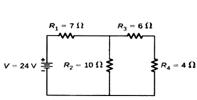
Answer:
R3 and R4 are in series.
Hence the equivalent resistance of those two = R5 = R3 + R4 = 10 ohms
R5 and R2 are in parallel. Let R6 be the equivalent resistance for them
Hence R6 = R5×R2R5+R2 = 10020 = 5 ohms
Now R1 and R2 are in series and hence the final equivalent resistance of the entire circuit is R = R1 + R6 = 12 ohms
By Ohm’s law, we know that V = IR, hence I = VR
Hence the current in the circuit is 2412A = 2 A.
Question 28.
Write difference between the series and parallel combination of resistance.
| Resistances in Series |
Resistances in Parallel |
| a) The effective resistance is always equal to the sum of individual resistances i.e. Rs = R1 + R2 + R3 |
a) The reciprocal of the equivalent resistance is equal to the sum of reciprocal of the individual resistance i.e.
1Rp = 1R1 + 1R2 + 1R3 |
| b) The current flowing through each resistance is same i.e. single path for the flow of current. |
b) The current divides among the resistance i.e. multiple paths are available for the flow of current. |
| c) The potential difference is different across different resistances. |
c) The potential difference is same across different resistances. |
Question 29.
A set of ‘n’ identical resistors each resistance R are connected in series and the effective resistance is found to be ‘X’. When these are connected in parallel, the effective resistance is found to be ‘Y’. Find the ratio of X and Y.
Answer:
In series combination Rs = X = R + R + R + n resistance.
X = nR
In parallel combination 1Rp = 1R + 1R + 1R .... n times.
⇒ 1Rp = nR
⇒ Rp = Rn = Y
⇒ XY = nRRn = n2
Question 30.
How are electric charge and current related ?
Answer:
Electric charge and current are related in the following ways :
- Electric charge is the property of matter that is responsible for producing electric forces. It can be positive or negative in nature.
- Electric current is the flow of electric charge through a conductor, such as a wire.
- The amount of current flowing through a conductor is directly proportional to the amount of charge passing through it over a given period of time.
- This relationship is expressed by the equation : I = Qt
where I is the current, Q is the charge, and t is the time.
- The SI unit for charge is the coulomb (C), and the SI unit for current is the ampere (A).
Question 31.
How is potential difference measured ?
Answer:
- The potential difference is measured using an instrument called a voltmeter.
- One volt is the potential difference between two points in a current-carrying conductor when 1 joule of work is done to move a charge of 1 coulomb from one point to the other.
- The potential difference is calculated by dividing the work done (W) by the charge (Q).
- The formula for potential difference is V = WQ.
- Potential difference is measured in volts (V).
Question 32.
Describe the concepts of electrical power, its unit, and commercial energy measurement.
Answer:
- Electrical Power : Power is the rate at which work is done. Its unit is the watt (W).
- Power Calculation : One watt is consumed when 1A of current flows at a potential difference of 1 V (W = V × I).
- Commercial Unit: Kilowatt-hour (kWh) is the commercial unit of electrical energy.
- Energy Calculation : 1 kWh = 3,600,000 joules (J) or 3.6 × 10⁶ J.
Question 33.
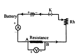
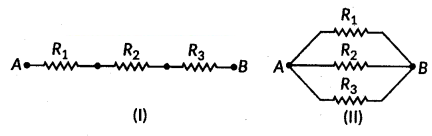
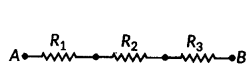
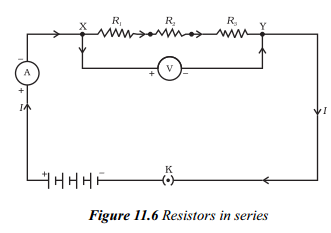
Read the paragraph and answer the questions.
In preceding sections, we learnt about some simple electric circuits. We have noticed how the current through a conductor depends upon its resistance and the potential difference across its
ends. In various electrical gadgets, we often use resistors in various combinations.
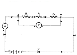
We now therefore intend to see how Ohm’s law can be applied to combinations of resistors. There are two methods of joining the resistors together. Figure shows an electric circuit in which three resistors having resistances R
1, R
2 and R
3 respectively, are joined end to end. Here the resistors are said to be connected in series.
i) When resistors are connected in series, what is the relationship between the total resistance and the individual resistances of the resistors ?
Answer:
According to Ohm’s law, the total resistance of resistors connected in series is equal to the sum of their individual resistances .
ii) In an electric circuit with resistors connected in series, how do you calculate the total resistance of the circuit ?
Answer:
The total resistance of the circuit is calculated by adding the individual resistances of the resistors.
iii) Using the example of an electric lamp and a conductor connected in series, calculate the potential difference across the electric lamp and conductor.
Answer:
The potential difference across the electric lamp is equal to the resistance of the lamp multiplied by the current, and the potential difference across the conductor is equal to the resistande of the conductor multiplied by the current.
Question 34.
Read the paragraph and answer the questions.
This is known as Joule’s law of heating. The law implies that heat produced in a resistor is (i) directly proportional to the square of current for a given resistance, (ii) directly proportional to resistance for a given current, and (iii) directly pro-portional to the time for which the current flows through the resistor. In practical situations, when an electric appliance is connected to a known voltage source, H=PRt is used after calculating the current through it, using the relation I = V/R.
i) What is Joule’s law of heating ?
Answer:
Joule’s law of heating states that the heat produced in a resistor is directly proportional to the square of the current for a given resistance, directly proportional to the resistance for a given current, and directly proportional to the time for which the current flows through the resistor.
ii) How can you calculate current using Ohm’s law ?
Answer:
Using Ohm’s law (V = IR), you can calculate the current flowing through a circuit by dividing the potential difference (V) across the circuit by the resistance (R) of the circuit.
iii) How can you calculate power in an electric circuit ?
Answer:
The power (P) dissipated in an electric circuit can be calculated using the equation P = VI, where V is the potential difference across the circuit and I is the current flowing through the circuit. This equation represents the rate at which electric energy is consumed in the circuit.
Question 35.
Consider a current I flowing through a resistor of resistance R. Let the potential difference across it be V (Fig). Let t be the time during which a charge Q flows across. The work done in moving the charge Q through a potential difference V is VQ. Therefore, the source must supply energy equal to VQ in time t. Hence the power input to the circuit by the source is P = V. Q/t = VI.
i) What is the equation for calculating the power input to a circuit by the source?
Answer:
The equation for calculating the power input to a circuit by the source is P = VI, where P is the power, V is the potential difference, and I is the current.
ii) How is the work done in moving a charge Q through a potential difference V calculated ?
Answer:
The work done in moving a charge Q through a potential difference V is calculated using the equation W = VQ.
iii) How is the energy supplied to a circuit by the source in time t calculated ?
Answer:
The energy supplied to a circuit by the source in time t is calculated by multiplying the power P by the time t, giving the equation E = Pt, where E is the energy.
Question 36.
Electric current is expressed by the amount of charge flowing through a particular area in unit time. In other words, it is the rate of flow of electric charges. In circuits using metallic wires, electrons constitute the flow of charges. However, electrons were not known at the time when the phenomenon of electricity was first observed. So, electric current was considered to be the flow of positive charges and the direction of flow of positive charges was taken to be the direction of electric current. Conventionally, in an electric circuit, the direction of electric current is taken as opposite to the direction of the flow of electrons, which are negative charges.
i) What is electric current and how is it expressed ?
Answer:
Electric current is the rate of flow of electric charges through a particular area in unit time. It is expressed by the amount of charge flowing through a conductor.
ii) What are the charges that constitute the flow of current in metallic wire circuits?
Answer:
Electrons constitute the flow of charges in metallic wire circuits.
iii) Why was electric current initially considered to be the flow of positive charges?
Answer:
Electrons were not known at the time when the phenomenon of electricity was first observed. Hence, electric current was considered to be the flow of positive charges.
iv) How is the direction of electric current conventionally determined in an electric circuit?
Answer:
The direction of electric current is conventionally determined as opposite to the di-rection of the flow of electrons, which are negative charges.
Question 37.
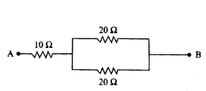
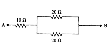
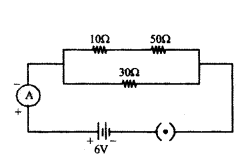
Calculate the equivalent resistance of the following electric circuit :
Answer:
- First, calculate the resistance of 2 series resistors inside the loop, i.e., = R1 + R2 = 10 Ω + 10 Ω = 20 Ω
- To calculate the equivalent resistance in the given electric circuit, let us find the parallel resistance.
- For that we use = R1×R2R1+R2 = 20Ω×20Ω20Ω+20Ω = 400Ω40Ω = 10 Ω
- Now, again applying the series formula to add the resistors together = 10 Ω + 10 Ω + 20 Ω = 40 Ω
- So the total resistance of the given 40 Ω.
Question 38.
The value of current (I) flowing through a given resistor of resistance (R), for the corresponding values of potential difference (V) across the resistor are as given below :
Plot a graph between current (I) and potential difference (V) and determine the resistance (R) of the resistor.
Answer:
Graph between current (I)
and potential difference (V).
Resistance of the resistor, R = V2?V1I2?I1
or R = 5-41.0-0.8 = 10.2 = 5Ω
Question 39.
In the given circuit determine the value of :
i) total resistance of the circuit
ii) current flowing through the ammeter.
Answer:
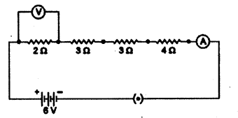
i) In the given circuit diagram, resistances of 10 Ω and 50 Ω are in series and resistance of 30 Ω connected in parallel with them.
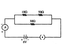
Therefore total resistance of the circuit (R)
1R = 110+50 + 130 = 1+260 = 360
∴ R = 603 Ω = 20 Ω
ii) Current flowing through the ammeter,
I = VR = 620 = 0.3A
Question 40.
Three resistors are connected as shown in the following figure.
Through the resistor 5 ohm, a current of 1 A is flowing.
a) What is the total resistance ?
b) What is the potential difference across AB and AC ?
c) What is the current through other two resistor’s ?

Answer:
R1 = 5Ω, R2 = 10Ω, R3 = 15Ω, I = 1 A
a) 1/R’ = 1/R2 + 1/R3 = 1/10 + 1/15 = 3+2/30 = 5/30
R’ = 305 = 6Ω
R = R1 + R’ = 5 + 6 = 11 W
Now, V = IR = 1 × 11 = 11 V
b) V1 = IR1 = 1 × 5 = 5V
Therefore V2 = V - V1 = 11 - 5 = 6 V
c) V2 ⇒ I1R2 ⇒ I1 = V2R2 = 610 = 0.6 A
I2 = V2R3 = 615 = 0.4 A
Question 41.
In the circuit shown in the figure; Find the power supplied by the battery. What is the potential differences across 4 Ω resistance ?
Answer:
4 Ω and 6 Ω resistances are short circuited. Therefore, no current will flow through these two resistances.
Current passing through the battery is I = 202 = 10A
This is also the current passing in wire AB from B to A.
Power supplied by the battery.
P = EI = (20) (10) = 200 Watt
Potential difference across 4 Ω resistance = Potential difference across 6 Ω resistance = 0
Question 42.
Write the formula for determining the equivalent resistance between A and B of the two combinations (I) and (II) of three resistors R1, R2 and R3 arranged as follows :
Answer:
i) From given R1, R2 and R3 are in series.
So, RAB = R1 + R2 + R3
ii) From given R1, R2 and R3 are in parallel.
Question 43.
Three resistors of 3 W each are connected to a battery of 3 V as shown. Calculate the current drawn from the battery.
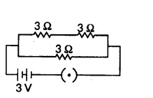
Answer:
As given in circuit diagram, two 3 Ω. resistors are connected in series to form R1.
So R1 = 3 Ω + 3 Ω = 6 Ω
And, R1 and R2 are in parallel combination, Hence, equivalent resistance of circuit (Req) given by
1Req = 1R1 + 1R2 ∴ 1Req = 16 + 13 = 1+26 = 36 = 12
Req = 2 Ω
Using Ohm’s law, V = IR
We get, 3V = I × 2 Ω or I = 32 A = 1.5 A
Current drawn from the battery is 1.5 A
Question 44.
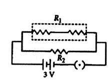
Three resistors in a circuit are attached as shown here resistance of F and G are 10 ohm and 5 ohm respectively. The resistance of E is unknown. There resistors are connected to a battery with potential difference 6 V.
a) What is the term used to describe such an arrangement of resistors ?
b) What is the resistance of E if 0.3 A current flows through it ?
c) What is the total current flowing in the circuit ?
Answer:
a) Resistance are attached in parallel.
b) Resistance of E = R1
I = VR ⇒ 0.3 = 6R ⇒ R1 = 60.3 = 20 Ω
c) Total current (I) = VR1 + VR2 + VR3 = 620 + 610 + 65 = 0.3 + 0.6 + 1.2 = 2.1 A
Question 45.
Calculate the effective resistance between A and B in the circuit given below :

Answer:
The effective resistance between A and B in the circuit is 0.33 ohms.
Explanation :
We have to calculate the effective resistance between A and B in the given circuit.
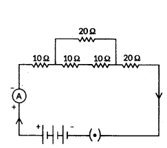
- Resistance of 4 ohms and 6 ohms are connected in series : = 4 + 6 = 10 Ohms
- Resistance of 3 ohms and 3 ohms are connected in series : = 3 + 3 = 6 Ohms
- Now, we can see that Resistance of 10 ohms, 15 ohms and 6 ohms are connected in parallel :
= 110 + 115 + 16 = 3+2+530 = 1030 = 13 ohm
Therefore, the effective resistance between A and B in the circuit is 0.33 ohms.
Question 46.
In the given circuit diagram calculate

i) the total effective resistance of the circuit.
ii) the current through each resistor.
Answer:
For the given circuit
R1 = 3 Ω, R2 = 4 Ω, R3 = 6 Ω and V = 6V.
i) Total effective resistance of the circuit, Req is given by
1Rp = 1R1
+ 1R2 + 1R3 = 13 + 14 + 16 = 912 or Req = 129Ω 43Ω = 1.33Ω
ii) Since, potential difference across each resistor connected in parallel is same.
So, V1 = V2 = V3 = 6 V
Apllying Ohm’s law,
V1 = I1R1 or I1 = V1R1 or I3 = 63A = 2A
Similarly, I2 = 6 A4 = 1.5 A and I3 = 66 A = 1 A
Question 47.
In the given circuit, A, B, C and D are four lamps connected with a battery of 60 V.
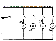
Analyse the circuit to answer the following questions.
i) What kind of combination are the lamps arranged in (series or parallel) ?
ii) Explain with reference to your above answer, what are the advantages (any two) of this combination of lamps.
iii) Explain with proper calculations which lamp glows the brightest,
iv) Find out the total resistance of the circuit.
Answer:
i) The lamps are in parallel.
ii) Advantages :
- In parallel connection, if one lamp is faulty, it will not affect the working of the other, lamps.
- They will also be using the full potential of the battery as they are 1 connected in parallel.
iii) In this case, all the bulbs have the same voltage. But lamp C has the highest current. Hence, For Lamp C, P = 5 × 60 W = 300 W (the maximum).
iv) The total current in the circuit = 3 + 4 + 5 + 3A = 15A
The Voltage = 60 V
V = IR and hence R = VI = 6015 A = 4 A
Extra Questions on Electricity Class 10 - 8 Marks
Question 1.
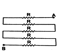
Deduce the expression for the equivalent resistance of three resistors connected in series.
Answer:
- If a number of resistors are joined end to end such that same current (i) flows through each of them, then the resistors are said to be connected in series.
- Consider three resistors R1, R2 and R3 connected in series and a potential difference (V) is applied across the combination as shown in figure.
- In series combination current remains constant and voltage is divided into V1, V2 and V3 across R1, R2 and R3 respectively.
i.e. V = V1 + V2 = 3 ______ (1)
- According to ohm’s law
Potential difference across R1 is V1 = IR1
Potential difference across R2 is V2 = IR2
Potential difference across R2 is V3 = IR3
- Let Req is the equivalent resistance of the combination of resistors in series we get
V = I R
- Substituting the values of V1, V2, V3 and V in the equation (1), we get
IRs = IR1 + IR2 + IR3
Rs = R1 + R2 + R3
- From above equation we can conclude that when several resistors are joined in series, the resistance of the combination Rs equals the sum of their individual resistances R1, R2, R3 and is thus greater than any individual resistance.
Question 2.
Deduce the expression for the equivalent resistance of three resistors connected in parallel.
Answer:
1) If a number of resistors are connected in between two common points such that the same voltage acts on all of them, then the resistors are said to connected in parallel.
2) Consider three resistors of resistances R1, R2 and R3 connected in parallel and a potential difference (V) is applied across the combination as shown in figure.
3) In parallel combination voltage remains constant and the current (I) gets divided into I1, I2 and I3 through R1, R2 and R3 respectively
i.e. I = I1 + I2 + I3 ______ (1)
4) According to ohm’s law
Current through R1 is I1 = VR1
Current through is R2 is I2 = VR2
Current through R3 is I3 = VR3
5) Let Rp be the equivalent resistance of the resistors in parallel, we get
I = VRp
6) Substituting the values of I1, I2, I3 and I in the equation (1), we get
VRp = VR1 + VR2 + VR3
1Rp = 1R1 + 1R2 + 1R3
7) Hence reciprocal of equivalent resistance is equal to sum of the reciprocals of individual resistances.
Question 3.
What is the relationship between potential difference, current, and resistance according to Ohm’s law ?
Answer:
According to Ohm’s law, the relationship between potential difference (V), current (I), and resistance (R) can be summarized as follows :
- Potential difference (V) is directly proportional to current (I), provided the resistance and temperature remain constant.
- This relationship can be expressed as V ∝ I or VI = constant.
- The constant of proportionality is the resistance (R) of the conductor.
- The resistance (R) is a property of the conductor that resists the flow of charges.
- The SI unit for resistance is ohm (Ω).
- If the potential difference across a conductor is 1 V and the current through it is 1 A, then the resistance of the conductor is 1 Ω
- Ohm’s-law can be further expressed as I = VR .
- Ohm’s law states that the potential difference across a conductor is directly proportional to the current flowing through it and inversely proportional to its resistance.
Question 4.
How does the heating effect of electric current convert useful electrical energy ?
Answer:
The heating effect of electric current converts useful electrical energy in the following ways :
- The generation of heat in a conductor is an inevitable consequence of electric current, and this heating effect can be undesirable as it converts useful electrical energy into heat.
- However, the heating effect of electric current also has many useful applications, such as in electric appliances like electric heaters, toasters, ovens, kettles, and electric irons.
- Joule’s law of heating states that the heat produced in a resistor is directly proportional to the square of the current, the resistance, and the time for which the current flows through the resistor.
- The heating effect of electric current is used in devices like fuses, which protect circuits and appliances by stopping the flow of excessive current.
- When the temperature of the fuse wire increases due to a larger current, it melts and breaks the circuit.
- The power consumed by an electric appliance can be calculated using the equation P = VI, where P is power, V is potential difference, and I is current.
- The energy supplied to the circuit by the source is dissipated as heat in resistive elements, such as in the heating coils of electric heaters or the filaments of bulbs.
- The potential difference across a resistor can be found using the relation V = IR, where V is potential difference, I is current, and R is resistance.
Question 5.
Explain Joule’s law of heating and its key principles.
Answer:
- Joule’s Law : It states that the heat produced in a resistor is determined by three factors.
- Proportional to Current Squared : Heat (H) is directly proportional to the square of the current (I) passing through the resistor.
- Proportional to Resistance : Heat is directly proportional to the resistance (R) of the resistor.
- Proportional to Time : Heat is directly proportional to the time (t) for which the current flows through the resistor.
- Formula : Mathematically, H = I2Rt represents Joule’s law of heating.
- Practical Application : This law is used in electric appliances, where heat is produced as a result of the electric current passing through resistors.
- Calculation : In practical scenarios, the current (I) is calculated using Ohm’s law (I = V/R), and then Joule’s law is applied to determine the heat produced (H = I2Rt).
Question 6.
How is the heating effect of electric current applied in the design of fuses used in electric circuits ?
Answer:
- Fuse Function : A fuse is designed to protect circuits and appliances by interrupting the flow of excessively high electric current.
- Mechanism : The fuse consists of a wire made of a specific metal or alloy with an appropriate melting point, like aluminium, copper, iron, or lead.
- Operation : When a current larger than the specified value flows through the circuit, the fuse wire heats up due to Joule’s heating effect.
- Melting and Breaking : The increased temperature melts the fuse wire, breaking the circuit and preventing damage to the connected devices.
- Encasement : The fuse wire is encased in a cartridge made of porcelain or similar material with metal ends.
- Rating : Fuses are rated based on the maximum current they can handle. Common ratings include 1 A, 2 A, 3 A, 5 A, 10 A, etc.
- Example Calculation : For an electric iron consuming 1 kW electric power at 220 V, a current of (1000/220) A, which is 4.54 A, flows. In this case, a 5 A fuse must be used to ensure safe operation.
Question 7.
Explain the significance of the V-I graph for a nichrome wire shown in Figure and how does it relate to Ohm’s law ?

Answer:
- Graph Significance : The V-I graph illustrates the relationship between potential difference (V) and current (I) in a nichrome wire.
- Linear Plot : The straight line on the graph indicates that as the current through the wire increases, the.potential difference across the wire also increases linearly.
- Ohm’s Law Connection : This linear relationship between V and I confirms Ohm’s law, Which states that the potential difference (V) across a conductor is directly proportional to the current (I) flowing through it.
- Ohm’s Law Recap : Ohm’s law can be mathematically expressed as V = I × R, where V is potential difference, I is current, and R is resistance. In this case, the graph’s straight line reaffirms the direct proportionality between V and I, supporting the principles of Ohm’s law.
Question 8.
Describe the significance of the V-I graph and how the resistance of a conductor is calculated using Ohm’s law.
Answer:
1) Significance of V - I Graph :
a) The V-I graph represents the relationship between potential difference (V) and current (I) in a circuit.
b) For most conductors, the V-I graph is a straight line passing through the origin, indicating that V is directly proportional to I, as per Ohm’s law.
c) The slope of the V-I graph represents the resistance (R) of the conductor. A steeper slope indicates higher resistance.
2) Calculation of Resistance using Ohm’s Law :
a) Using Ohm’s Law Equation : Ohm’s law equation ( V = IR) can be rearranged to calculate resistance: R = V/I.
b) Experimental Setup : Measure the potential difference (V) across the conductor and the current (I) passing through it using appropriate instruments.
c) Calculating Resistance: Substitute the measured values of V and I into the formula R = V/I to calculate the resistance of the conductor in ohms (Omega).
Question 9.
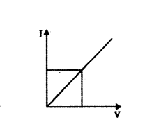
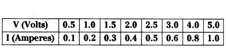
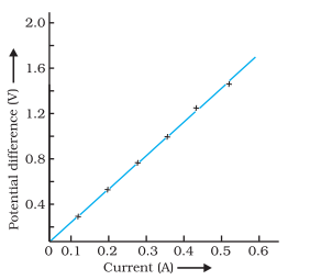
Study the V-I graph for a resistor as shown in the figure and prepare a table showing the values of l (in amperes) corresponding to four different values V (in volts). Find the value of current for V = 10 volts. How can we determine the resistance of the resistor from this graph ?
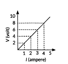
Answer:
Since, the graph is straight line so we can either extrapolate the data or simply mark the value from graph as shown in figure.
| Current, I(A) |
Voltage, V(V) |
| 0 |
0 |
| 1 |
2 |
| 2 |
4 |
| 3 |
6 |
| 4 |
8 |
Hence, the value of current for V = 10 volts is 5 amperes (or 5 A).
From Ohm’s law, V = IR,
We can write, R =
VI
At any point on the graph, resistance is the ratio of values of V and I. Since, the given graph is straight line (ohmic conductor) so, the slope of graph will also give the resistance of R =
10 V5 A = 2 Ω
Alternately, R =
(8?2)V(4?1)A =
6 V3 A = 2Ω
Question 10.
a) With the help of a suitable circuit diagram prove that the reciprocal of the equivalent resistance of a group of resistance joined in parallel is equal to the sum of the reciprocals of the individual resistance,
b) In an electric circuit two resistors 12 Ω each are joined in parallel to a 6 V battery. Find the current drawn from the battery.
Answer:
a) Let there are n resistances, each of value R1, R2 ... Rn are respectively, are connected in parallel to a battery of voltage V.
The equivalent resistance is defined by Req = Vi ⇒ VReq
As all the resistors are connected in parallel, so voltage across them is same. The current is divided into i1, i2, i3,.... in
Net current, i = i1 + i2 + i3 + .... +in
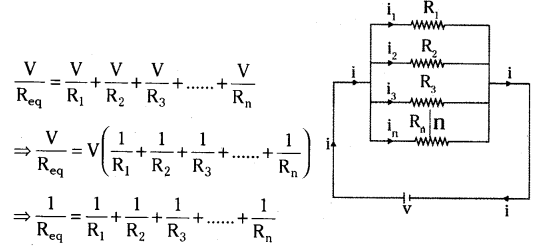
Thus, the reciprocal of the equivalent resistance of a group of resistance joined in parallel is equal to the sum of the reciprocal of the individual resistances.
b) Given, Voltage of the battery, V = 6V
Resistance of resistors, R = 12 Ω
Using 1/R = 1/R + 1/R ⇒ 1/R = 1/12 + 1/12 = 2/12 = 1/6 ⇒ R’ = 6Ω
I = V/R ⇒ I = 6 V/6Ω = 1A
Question 11.
All electric lamp of resistance 20 Ω and a conductor of resistance 4 Ω are connected to a 6V battery as shown in the circuit. Calculate :
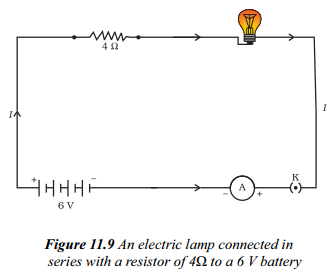
a) the total resistance of the circuit.
b) the current through the circuit.
c) the potential difference across the (i) electric lamp and (ii) conductor, and
d) power of the lamp.
Answer:
a) As electric lamp of resistance 20 Ω and a conductor of resistance 4 Ω are connected in series.
∴ Equivalent resistance, R = R1 + R2 ⇒ R = 20 Ω + 4 Ω = 24 Ω
b) Voltage of the battery, V = 6V
Current through the circuit, I = VRΩ
⇒ I = 6 V24Ω = 14A ⇒ I = 0.25 A
c) On applying Ohm’s law to the electric lamp and resistor separately, we get potential difference across the electric lamp
V1 = IR1 ⇒ V1 = 0.25 A × 20 Ω = 5 V
and across the conductor
V2 = IR2 = 0.25 A × 4Ω = 1 V
d) Power of the lamp, P = V21R1 ⇒ P = (5)220 = 2520 = 1.25W
Question 12.
Draw a schematic diagram of a circuit consisting of a battery of 3 cells of 2 V each, a combination of three resistors of 10 Ω, 20 Ω and 30 Ω connected in parallel, a plug key and an ammeter, all connected in series. Use this circuit to find the value of the following :
a) Current through each resistor
b) Total current in the circuit
c) Total effective resistance of the circuit.
Answer:
The circuit diagram is as shown below.
a) Given, voltage of the battery = 2V + 2V + 2V = 6V
Current through 10 Ω resistance, I10 = VR = 610 = 0.6 A
Current through 20 Ω resistance, I20 = VR = 620 = 0.3 A
Current through 30 Ω resistance, I30 = VR = 630 = 0.2 A
b) Total current in the circuit, 1 = I10 + I20 + I30 = 0.6 + 0.3 + 0.2 = 1.1 A
c) Total resistance of the circuit, 1Rp = 110 + 120 + 130 = 1160
Question 13.
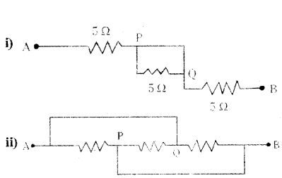
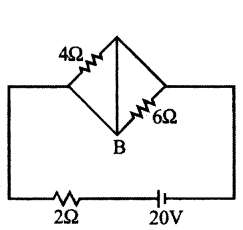
Two wires A and B are of equal length and have equal resistances. If the resistivity of A is more than that of B, which wire is thicker and why ? For the electric circuit given calculate :
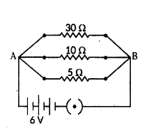
i) current in each resistor,
ii) total current drawn from the battery, and
iii) equivalent resistance of the circuit.
Answer:
Let IA, ρA and RA be the length, area of cross-section and resistance of wire A and IB, ρB and RB are that of wire B.
Here, IA = IBand RA = RB
If ρA and ρB are the resistivities of wire A and B respectively then
Since pA > pB therefore aA > aB Hence, wire A is thicker than wire B.
For parallel combination, V1 = V2 = V3 = 6V
i) Using Ohm’s law :
i1 = V1R1 = 630 = 0.2 A ; i2 = V2R2 = 610 = 0.6 A ; i3 = V3R3 = 65 = 0.6 A ;
ii) Total current drawn from battery, I = I1 + I2 + I3 = 0.2 + 0.6 + 1.2 = 2 A
iii) Equivalent resistance of the circuit, Req can be obtained by Ohm’s law V = I Req
So, 6 V = 2 A × Req or Req = 62 = 3 Ω
Aliter, 1Req = 1R1 + 1R2 + 1R3 ⇒ 130 + 110 + 15 = 1+3+630 = 1030 = 13 or Req = 30

Question 14.
Vinita and Ahmed demonstrated a circuit that operates the two headlights and the two sidelights of a car, in their school exhibition.
Based on their demonstrated cir-cuit, answer the following questions.
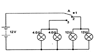
Questions :
a) State what happens when switch A is connected to
i) Position 2
ii) Position 3
b) Find the potential difference across each lamp when lit.
c) Calculate the current
i) in each 12 Ω lamp when lit.
ii) in each 4 Ω lamp when lit.
d) Show with calculations which type of lamp, 4.0 Ω or 12 Ω, has the higher power.
Answer:
a) i) 12 Ω lamps (only) on.
ii) 4 Ω lamps (only) on.
b) 12 V for both sets of lamps and all of them are in parallel,
c) i) 12 Ω lamps are on when the wire is connected to position 2.
Voltage across both 12 Ω lamps = 12 V.
V = 1R (Ohm’s law) ; I = VR = 1212 = 1A
ii) 4 Ω lamps are on when the wire is connected to position 3.
Voltage across both 4 Ω lamps = 12 V
V = IR (Ohm’s law) ; I = VR = 124 = 3A
d) P = V2R
All lamps are in parallel and hence same V for all lamps.
For 4 Ω lamps → P = 12×124
For 12 Ω lamps → P = 12×1212
Hence 4 Ω lamps will have higher power.
Question 15.
Study the following electric circuit in which the resistors are arranged in three arms A, B and C.
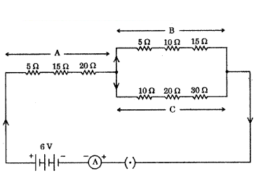
Questions :
a) Find the equivalent resistance of arm A.
h) Calculate the equivalent resistance of the parallel combination of the arms B and C,
c) i) Determine the current that flows through the ammeter.
ii) Determine the current that flows in the ammeter when the arm B is withdrawn from the circuit
Answer:
a) Equivalent resistance of arm A = RA = R1 + R2 + R3 (as in series)
RA = 5 Ω + 15 Ω + 20 Ω = 40 Ω
So equivalent resistance arm A is 40 Ω.
b) Equivalent resistance of arm B = RB = 5 Ω + 10 Ω + 15 Ω = 30 Ω (as in series)
Equivalent resistance of arm C = RC = 10 Ω + 20 Ω + 30 Ω = 60 Ω (as in series)
RB and RC are in parallel 1RC = 130 + 160 ⇒ 1R = 2+160 ⇒ RC 603 = 20 Ω
c) i)
so total current = RC + RA = R(as in series)
20 Ω + 40 Ω = 60 Ω
Potential difference = 6V
By Ohm’s law V = IR ⇒ I = VR = 660 = 110 = 0.1A.
ii) When arm B was withdrawn, then
Toted current RT = RA + RC (in series)
Now RT = 40 Ω + 60 Ω = 100 Ω
By ohm’s law I = VR = 6100