NCERT CBSE for Class 10 Science Chapter 12 Electricity Important Questions
Question 1.
A current of 10 A flows through a conductor for two minutes?
Year of Question :(Board Term I, 2013)
- (i) Calculate the amount of charge passed through any area of cross section of the conductor
- (ii) If the charge of an electron is 1.6 × 10⁻¹⁹ C, then calculate the total number of electrons flowing.
Answer:
Given that: I = 10 A, t = 2 min = 2 × 60 s = 120 s
- (i) Amount of charge Q passed through any area of cross-section is given by I = Qt
or Q = I × t/Q = (10 × 120) A s = 1200 C
- (ii) Since, Q = ne
where n is the total number of electrons flowing and e is the charge on one electron
∴ 1200 = n × 1.6 × 10⁻¹⁹
or n = 1200/1.6×10-19 = 7.5 × 10²¹
Question 2.
Define electric current?
Year of Question :(2017)
Answer:
Electric current is the amount of charge flowing through a particular area in unit time
Question 3.
Define one ampere?
Year of Question :(2015)
Answer:
One ampere is constituted by the flow of one coulomb of charge per second.
1 A = 1 C s-1
Question 4.
Name a device that you can use to maintain a potential difference between the ends of a conductor. Explain the process by which this device does so?
Year of Question :(2015)
Answer:
A cell or a battery can be used to maintain a potential difference between the ends of a conductor. The chemical reaction within a cell generates the potential difference across the terminals of the cell, even when no current is drawn from it. When it is connected to a conductor, it produces electric current and, maintain the potential difference across the ends of the conductor
Question 5.
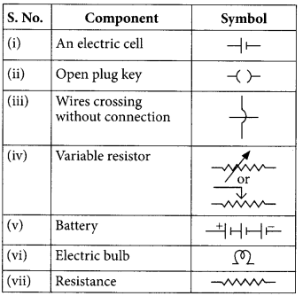
Draw the symbols of commonly used components in electric circuit diagrams for?
Year of Question :(4/5, Board Term 1,2017)
- (i) An electric cell
- (ii) Open plug key
- (iii) Wires crossing without connection
- (iv) Variable resistor
- (v) Battery
- (vi) Electric bulb
- (vii) Resistance
Answer:
Question 6.
A student plots V-I graphs for three samples of nichrome wire with resistances R1, R2 and R3. Choose from the following the statements that holds true for this graph?
Year of Question :(2020)
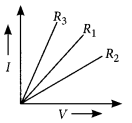
- (a) R1 = R2 = R3
- (b) R1 > R2 > R3
- (c) R3 > R2 > R1
- (d) R2 > R1 > R3
Answer:
- (d) : The inverse of the slope of I-V graph gives the resistance of the material. Here the slope of -Rj is highest. Thus, R2 > R1 > R3
Question 7.
State Ohms law?
Year of Question :(2019)
Answer:
It states that the potential difference V, across the ends of a given metallic wire in an electric circuit is directly proportional to the current flowing through it, provided its temperature remains the same. Mathematically,
V ∝ I
V = RI
where R is resistance of the conductor
Question 8.
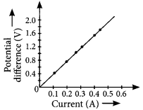
A V-I graph for a nichrome wire is given below. What do you infer from this graph? Draw a labelled circuit diagram to obtain such a graph?
Year of Question :(2020)
Answer:
As graph is a straight line, so it is clear from the graph that V ∝ I.
 The shape of the graph obtained by plotting potential difference applied across conductor against the current flowing v. llmuigh il will be a straight line.
According to ohms law,
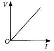 V = IR or R = V/I
So, the slope of V-/ graph at any point represents the resistance of the given conductor
Question 9.
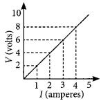
Study the V-I graph for a resistor as shown in the figure and prepare a table showing the values of I (in amperes) corresponding to four different values V (in volts). Find the value of current for V = 10 volts. How can we determine the resistance of the resistor from this graph?
Year of Question :(2012)
Answer:
Since, the graph is straight line so we can either extrapolate the data or simply mark the value from graph as shown in figure
| Current, I(A) |
Voltage, V(V) |
| 0 |
0 |
| 1 |
2 |
| 2 |
4 |
| 3 |
6 |
| 4 |
8 |
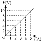
Hence, the value of current for V = 10 volts is 5 amperes (or 5 A).
From Ohms law, V = IR,
We can write, R = V/I
At any point on the graph, resistance is the ratio of values of V and I. Since, the given graph is straight line (ohmic conductor) so, the slope of graph will also give the resistance of the resistor
R = 10V/5A = 2Ω
Alternately, R = (8-2)V/(4-1)A = 6V/3A = 2 Ω
Question 10.
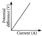
V-I graph for a conductor is as shown in the figure
 ?
?
Year of Question :(Board Term I, 2014)
- (i) What do you infer from this graph
- (ii) State the law expressed here.
Answer:
- (i) As graph is a straight line, so it is clear from the graph that V ∝ I.
 The shape of the graph obtained by plotting potential difference applied across conductor against the current flowing v. llmuigh il will be a straight line.
According to ohms law,
 V = IR or R = V/I
So, the slope of V-/ graph at any point represents the resistance of the given conductor
- (ii) It states that the potential difference V, across the ends of a given metallic wire in an electric circuit is directly proportional to the current flowing through it, provided its temperature remains the same. Mathematically,
V ∝ I
V = RI
where R is resistance of the conductor
Question 11.
State Ohms law. Draw a labelled circuit diagram to verify this law in the laboratory. If you draw a graph between the potential difference and current flowing through a metallic conductor, what kind of curve will you get? Explain how would you use this graph to determine the resistance of the conductor?
Year of Question :(2016)
Answer:
As graph is a straight line, so it is clear from the graph that V ∝ I.
 The shape of the graph obtained by plotting potential difference applied across conductor against the current flowing v. llmuigh il will be a straight line.
According to ohms law,
 V = IR or R = V/I
So, the slope of V-/ graph at any point represents the resistance of the given conductor
Question 12.
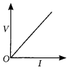
State and explain Ohms law. Define resistance and give its SI unit. What is meant by 1 ohm resistance? Draw V-I graph for an ohmic conductor and list its two important features?
Year of Question :(2012)
Answer:
Resistance : It is ihe properly of a conductor lo resist the How of charges through it.
Its SI unit is ohm (Ω). If the potential difference across the two ends of a conductor is 1 V and the current through it is 1 A, then the resistance R, of the conductor is 1 ohm (1 Ω). lvolt
1 ohm = 1volt/1ampere
V-I graph for an ohmic conductor can be drawn as given in figure.
 Important feature of V-I graph are:
(i) It is a straight line passing through origin.
(ii) Slope of V-I graph gives the value of resistance of conductor slope = R = V/I
Question 13.
Assertion (A) : The metals and alloys are good conductors of electricity.
Reason (R) : Bronze is an alloy of copper and tin and it is not a good conductor of electricity?
Year of Question :(2012)
- (a) Both (A) and (R) are true and (R) is the correct explanation of the assertion (A)
- (b) Both (A) and (R) are true, but (R) is not the correct explanation of the assertion (A).
- (c) (A) is true, but (R) is false.
- (d) (A) is false, but (R) is true. (2020)
Answer:
- (c) : Metals and alloys are good conductors of electricity. Bronze is an alloy of copper and tin which are metals and thus is a good conductor of electricity
Question 14.
A cylindrical conductor of length l and uniform area of cross section A has resistance R. The area of cross section of another conductor of same material and same resistance but of length 2l is ?
Year of Question :(2020)
- (a) A/2
- (b) 3A/2
- (c) 2A
- (d) 3A
Answer:
- (c) : The resistance of a conductor of length!, and area of cross section, A is
R = ρlA
where ρ is the resistivity of the material.
Now for the conductor of length 21, area of cross-section A and resistivity ?.
R = ρl/A = ρ2l/A
But given, R = R ⇒ ρl/A = ρ2l/A or A = 2A
Question 15.
Assertion (A) : Alloys are commonly used in electrical heating devices like electric iron and heater.
Reason (R): Resistivity of an alloy is generally higher than that of its constituent metals but the alloys have low melting points then their constituent metals?
Year of Question :(2012)
- (a) Both (A) and (R) are true and (R) is the correct explanation of the assertion (A)
- (b) Both (A) and (R) are true, but (R) is not the correct explanation of the assertion (A)
- (c) (A) is true, but (R) is false.
- (d) (A) is false, but (R) is true. (2020)
Answer:
- (a) Both (A) and (R) are true and (R) is the correct explanation of the assertion (A)
Question 16.
How is the resistivity of alloys compared with those of pure metals from which they may have been formed?
Year of Question :(2017)
Answer:
The resistivity of an alloy is generally higher than that of its constituent metals
Question 17.
- (i) List three factors on which the resistance of a conductor depends
- (ii) Write the SI unit of resistivity. (Board Term 1, 2015)
Answer:
- (i) Resistance of a conductor depends upon the following factors
- (1) Length of the conductor : (Treater the length (I) of the conductor more will be the resistance (R).
R ∝ I
- (2) Area ol cross section of the conductor: (Ireater the cross-sectional area of the conductor, less will be the resistance.
R ∝ 1/A
- (3) Nature of conductor.
- (ii) SI unit of resistivity is Ω m.
Question 18.
Calculate the resistance of a metal wire of length 2m and area of cross section 1.55 × 10⁶ m², if the resistivity of the metal be 2.8 × 10⁻⁸ Ωm
Year of Question :(2013)
Answer:
For the given metal wire,
length, l = 2 m
area of cross-section, A = 1.55 × 10⁻⁶ m²
resistivity of the metal, p = 2.8 × 10⁻⁸ Ω m
Since, resistance, R = ρl/A
So R = (2.8×10-8×2/1.55×10-6)Ω
= 5.61.55 × 10-2 Ω = 3.6 × 10⁻²Ω or R = 0.036Ω
Question 19.
- (a) List the factors on which the resistance of a conductor in the shape of a wire depends.
- (b) Why are metals good conductors of electricity whereas glass is a bad conductor of electricity ? Give reason.
- (c) Why are alloys commonly used in electrical heating devices ? Give reason.
Year of Question : (2018)
Answer:
- (i) Resistance of a conductor depends upon the following factors
- (1) Length of the conductor : (Treater the length (I) of the conductor more will be the resistance (R).
R ∝ I
- (2) Area ol cross section of the conductor: (Ireater the cross-sectional area of the conductor, less will be the resistance.
R ∝ 1/A
- (3) Nature of conductor.
- (ii) SI unit of resistivity is Ω m.
(b) Metal have very low resistivity and hence they are good conductors of electricity.
Whereas glass has very high resistivity so glass is a bad conductor of electricity
(c) Alloys are commonly used in electrical heating devices due to the following reasons
(i) Alloys have higher resistivity than metals
(ii) Alloys do not get oxidised or burn readily
Question 20.
Calculate the resistivity of the material of a wire of length 1 m, radius 0.01 cm and resistance 20 ohms?
Year of Question :(2017)
Answer:
We are given, the length of wire, l = 1 m, radius of wire, r = 0.01 cm = 1 × 10⁻⁴ m and resistance, R = 20Ω As we know,
R = ρl/A, where ρ is resistivity of the material of the wire.
∴ 20Ω.= ρ l/πr² = ρ1 m/3.14×(10-4)² m²
∴ ρ = 6.28 × 10⁻⁷ Ω m
Question 21.
A copper wire has diameter 0.5 mm and resistivity 1.6 × 10⁻⁸ Ω m. Calculate the length of this wire to make it resistance 100 Ω. How much does the resistance change if the diameter is doubled without changing its length?
Year of Question :(2015)
Answer:
Given; resistivity of copper = 1.6 × 10⁻⁸ Ω m, diameter of wire, d = 0.5 mm and resistance of wire, R = 100 Ω
Radius of wire, r = d/2 = 0.5/2 mm
= 0.25 mm = 2.5 × 10⁻⁴ m
Area of cross-section of wire, A = nr²
∴ A = 3.14 × (2.5 × 10-4)²
= 1.9625 × 10⁻⁷ m²
= 1.9 × 10⁻⁷ m²
As, R = ρl/A
∴100 Ω = 1.6×10?8Ωm×l/1.9×10-7 m²
l = 1200 m
If diameter is doubled (d’ = 2d), then the area of cross-section of wire will become
A’ = πr² = π(d’2)² = π(2d2)² = 4A
Now R ∝ 1/A, so the resistance will decrease by four times or new resistance will be
R’ = R/4 = 100/4 = 25Ω
Question 22.
The resistance of a wire of 0.01 cm radius is 10Ω. If the resistivity of the material of the wire is 50 × 10-8 ohm meter, find the length of the wire?
Year of Question :(2014)
Answer:
Here, r = 0.01 cm = 10-4 m, ρ = 50 × 10-8 Ω m and R = 10 Ω
As, R = ρl/A
or l = RA/ρ=R/ρ(πr²)
so l = 1050×10?83.14×(10-4)²
= 0.628 m = 62.8 cm
Question 23.
A wire has a resistance of 16Ω. It is melted and drawn into a wire of half its original length. Calculate the resistance of the new wire. What is the percentage change in its resistance?
Year of Question :(2013)
Answer:
When wire is melted, its volume remains same, so,
V = V or A‘l’ = Al
Here, l’ = l/2
Therefore, A’ = 2 A
Resistance, R = ρl/A = 16Ω
Now, R = ρl/A=ρ(l/2)/2A=1/4ρl/A
So, R = R/4 = 16/4 = 4 Ω
Percentage change in resistance,
= (R-R/R)×100=(16-4/16) × 100 = 75%
Question 24.
If the radius of a current carrying conductor is halved, how does current through it change?
Year of Question :(2014)
Answer:
If the radius of conductor is halved, the area of cross-section reduced to (14) of its previous value.
Since, R ∝ 1A, resistance will become four times
From Ohms law, V = IR
For given V, I ∝ 1/R
So, current will reduce to one-fourth of its previous value
Question 25.
Define resistance of a conductor. State the factors on which resistance of a conductor depends. Name the device which is often used to change the resistance without changing the voltage source in an electric circuit. Calculate the resistance of 50 cm length of wire of cross sectional area 0.01 square mm and of resistivity 5 × 10⁻⁸ ? m.?
Year of Question :(2014)
Answer:
Resistance is the property of a conductor to resist the flow of charges through it.
Factors affecting resistance of a conductor:
Rheostat is the device which is often used to change the resistance without changing the voltage source in an electric circuit.
We are given, length of wire, l = 50 cm = 50 × 10-2 m cross-sectional area, A = 0.01 mm²
= 0.01 × 10⁻⁶ m²
and resistivity, ρ = 5 x 10⁻⁸ Ω m.
As, resistance, R = ρl/A
∴ R = (5×10-8×50×10-2/0.01×10-6) Ω
= 2.5 Ω
Question 26.
If a person has five resistors each of value 1/5 Ω, then the maximum resistance he can obtain by connecting them is?
Year of Question :(2020)
- (a) 1 Ω
- (b) 5 Ω
- (c) 10 Ω
- (d) 25 Ω
Answer:
- (a) The maximum resistance can be obtained from a group of resistors by connecting them in series. Thus,
Rs = 15+15+15+15+15 1 Ω
Question 27.
The maximum resistance which can be made using four resistors each of 2 Ω is
Year of Question :(2012)
- (a) 2 Ω
- (b) 4 Ω
- (c) 8 Ω
- (d) 16 Ω (2020)
Answer:
- (c)A group of resistors can produce maximum resistance when they all are connected in series.
∴ Rs = 2 Ω + 2 Ω + 2 Ω + 2 Ω = 8 Ω
Question 28.
The maximum resistance which can be made using four resistors each of resistance 1/2 Ω is
Year of Question :(2020)
- (a) 2 Ω
- (b) 1 Ω
- (c) 2.5 Ω
- (d) 8 Ω
Answer:
- (a) The maximum resistance can be produced from a group of resistors by connecting them in series.
Thus, Rs = 1/2 Ω + H 1/2 Ω + 1/2 Ω + 1/2 Ω = 2 Ω
Question 29.
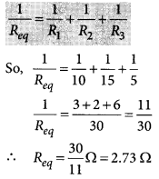
Three resistors of 10 Ω, 15 Ω and 5 Ω are connected in parallel. Find their equivalent resistance.?
Year of Question :(2014)
Answer:
Here, R1 = 10 Ω, R2 =15 Ω, R3 = 5 Ω.
In parallel combination, equivalent resistance, (Req) is given by
Question 30.
List the advantages of connecting electrical devices in parallel with an electrical source instead of connecting them is series?
Year of Question :(2013)
Answer:
- (a) When a number of electrical devices are connected in parallel, each device gets the same potential difference as provided by the battery and it keeps on working even if other devices fail. This is not so in case the devices are connected in series because when one device fails, the circuit is broken and all devices stop working
- (b) Parallel circuit is helpful when each device has different resistance and requires different current for its operation as in this case the current divides itself through different devices. This is not so in series circuit where same current flows through all the devices, irrespective of their resistances
Question 31.
Show how would you join three resistors, each of resistance 9 Ω so that the equivalent resistance of the combination is (i) 13.5 Ω, (ii) 6 Ω
Year of Question :(2018)
Answer:
- (i) The resistance of the series combination is higher than each of the resistances. A parallel combination of two 9 Ω resistors is equivalent to 4.5 Ω. We can obtain 13.5 Ω by coupling 4.5 Ω and 9 Ω in series. So, to obtain 13.5 Ω, the combination is as shown in figure (a).

- (ii) To obtain a equivalent resistance of 6 Ω, we have to connect two 9 Ω resistors in series and then connect the third 9 Ω resistor in parallel to the series combination as shown in the figure (b).

Question 32.
Three resistors of 3 Ω each are connected to a battery of 3 V as shown. Calculate the current drawn from the battery?
Year of Question :(2017)

Answer:
As given in circuit diagram, two 3 Ω resistors are connected in series to form R1; so R1 = 3 Ω + 3 Ω = 6 Ω
And, R1 and R2 are in parallel combination, Hence, equivalent resistance of circuit (Req) given by
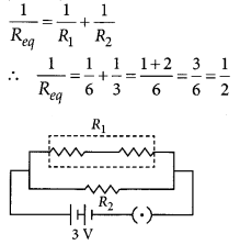 Req = 2 Ω
Using Ohms law, V = IR
We get,
3 V = I × 2 Ω
or I = 32 A = 1.5 A
Current drawn from the battery is 1.5 A
Question 33.
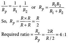
Two identical resistors are first connected in series and then in parallel. Find the ratio of equivalent resistance in two cases?
Year of Question :(2012)
Answer:
Let resistance of each resistor be R.
For series combination,
Rs = R1 + R2
So, Rs = R + R = 2R
For parallel combination,
Question 34.
- (a) A 6 Ω resistance wire is doubled on itself. Calculate the new resistance of the wire
- (b) Three 2 Ω resistors A, B and C are connected in such a way that the total resistance of the combination is 3 Ω. Show the arrangement of the three resistors and justify your answer. (2020)
Answer:
- (a) Given resistance of wire, R = 6 Ω
Let l be the length of the wire and A be its area of
cross-section. Then
R = ρl/A = 6 ?
Now when the length is doubled, l = 2l and A = A/2
∴ R = ρ(2l)/A/2=4ρl/A = 4 × 6 Ω = 24 Ω
- (b) Given the total resistance of the combination = 3 Ω
In order to get a total resistance of 3 Ω, the three resistors has to be connected as shown.
 Such that, 1/RP=1/2+1/2 = 1
⇒ Rp = 1 Ω
and Rs = 2 Ω + 1 Ω = 3 Ω
Question 35.
Draw a schematic diagram of a circuit consisting of a battery of 3 cells of 2 V each, a combination of three resistors of 10 ?, 20 ? and 30 ? connected in parallel, a plug key and an ammeter, all connected in series. Use this circuit to find the value of the following ?
Year of Question :(2012)
- (a) Current through each resistor
- (b) Total current in the circuit
- (c) Total effective resistance of the circuit. (2020)
Answer:
The circuit diagram is as shown below
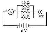
- (a) Given, voltage of the battery = 2V + 2V + 2V = 6 V
Current through 10 Ω resistance,
I10 = V/R=6/10 = 0.6 A
Current through 20 Ω resistance,
I20 = VR=620 = 0.3 A
Current through 30 Ω resistance,
I30 = VR=630 = 0.2 A
- (b) Total current in the circuit, 1= I10 + I20 + I30
= 0.6 + 0.3 + 0.2 = 1.1 A
(c) Total resistance of the circuit,
1/Rp=1/10+1/20+1/30=11/60
Question 36.
- (a) With the help of a suitable circuit diagram prove that the reciprocal of the equivalent resistance of a group of resistances joined in parallel is equal to the sum of the reciprocals of the individual resistances
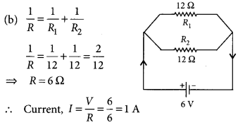
- (b) In an electric circuit two resistors of 12 ? each are joined in parallel to a 6 V battery. Find the current drawn from the battery. (Delhi 2019)
Answer:
- (a) Resistors in parallel : When resistors are connected in parallel.
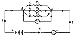
- (i) The potential difference across their ends is the same
- (ii) The sum of current through them is the current drawn from the source of energy or cell.
I = I1 + I1 + I3 or V/Rp=V/R1+V/R2+V/R3
- (iii) The equivalent resistance is given by,
1/Rp=1/R1+1/R2+1/R3
Hence equivalent resistance in parallel combination is equal to the sum of reciprocals of the individual resistances
Question 37.
For the series combination of three resistors current in each resistor, establish the relation R = R1 + R2 + R3 where the symbols have their usual meanings. Calculate the equivalent resistance of the combination of three resistors of 6Ω, 9 Ωand 18 Ωjoined in parallel?
Year of Question :(2017)
Answer:
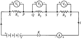 Given figure shows the series combination of three resistors R1, R2 and R3 connected across a voltage source of potential difference V.
Let current I is flowing through the circuit.
V1, V2 and V3 are the potential differences across resistors R1, R2 and R3 respectively.
Since, the total potential difference across a combination of resistors in series is equal to the sum of potential difference across the individual resistors.
∴ v = V1, V2 and V3.(i)
In series current through each resistor is same. Applying the Ohms law,
V1 = IR1, V2 = IR2 and V3 = IR1 ....(ii)
If Rs is the equivalent resistance of the circuit, then
V = IRs .(iii)
From eqns. (i), (ii) and (iii),
we can write IRs = IR1 + IR2 + IR3
or Rs = R1 + R2 + R3
We can conclude that when several resistors are joined in series, the resistance of the combination Rs equals the sum of their individual resistances,
R1, R2 and R3
Given : R1 = 6 Ω, R2 = 9 Ω,
R3 = 18 Ω are connected in parallel.
Equivalent resistance, Req, is given by
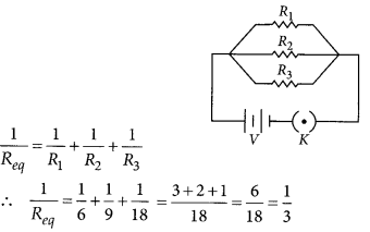 or Req = 3 Ω
Question 38.
State ohms law. Represent it graphically. In the given circuit diagram calculate?
Year of Question :(2012)
- (i) the total effective resistance of the circuit
- (ii) the current through each resistor
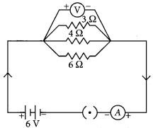
Answer:
Graphical representation of Ohms law
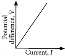 For the given circuit
R1 = 3 Ω, R2 = 4 Ω., R3 = 6 Ω and V = 6V
- (i) Total effective resistance of the circuit, Req is given by
1/Req=1/R1+1/R2+1/R3=1/3+1/4+1/6=9/12
or Req = 12/9 Ω = 4/3 Ω = 1.33 Ω
- (ii) Since, potential difference across each resistor connected in parallel is same.
So, V1 = V2 = V3 = 6 V
Applying Ohms law,
V1 = I1R1 or I1 = V1/R1 or I3 = 6/3 A = 2A
Similarly, I2 = 6A/4 = 1.5 A and I3 = 6/6 A = 1 A
Question 39.
- (a) Prove that the equivalent resistance of three resistors R1, R2 and R3 in series is R1 + R2 + R3
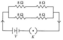
- (b) You have four resistors of 8 Ω each. Show how would you connect these resistors to have effective resistance of 8 Ω (4/5, Board Term I, 2015)
Answer:
 Given figure shows the series combination of three resistors R1, R2 and R3 connected across a voltage source of potential difference V.
Let current I is flowing through the circuit.
V1, V2 and V3 are the potential differences across resistors R1, R2 and R3 respectively.
Since, the total potential difference across a combination of resistors in series is equal to the sum of potential difference across the individual resistors.
∴ v = v1 + v2 + v3 .(i)
In series current through each resistor is same. Applying the Ohms law,
V1 = IR1, V2 = IR2 and V3 = IR1 ....(ii)
If Rs is the equivalent resistance of the circuit, then
V = IRs .(iii)
From eqns. (i), (ii) and (iii),
we can write IRs = IR1 + IR2 + IR3
or Rs = R1 + R2 + R3
We can conclude that when several resistors are joined in series, the resistance of the combination Rs equals the sum of their individual resistances,
R1, R2 and R3
Given : R1 = 6 Ω, R2 = 9Ω,
R3 = 18 Ω are connected in parallel.
Equivalent resistance, Req, is given by
 or Req = 3 Ω
- (b) If you have four 8 Ω resistors and the effective resistance is also 8 Ω then the two 8 Ω resistors are connected in series. Now you have pair of two 16 Ω resistors (8 Ω + 8 Ω). If you connect these resistors in parallel, you will have net resistance 8 ?.
Question 40.
Draw a labelled circuit diagram showing three resistors R1, R2 and R3 connected in series with a battery (E), a rheostat (Rh), a plug key (K) and an ammeter (A) using standard circuit symbols. Use this circuit to show that the same current flows through every part of the circuit. List two precautions you would observe while performing the experiment?
Year of Question :(2014)
Answer:
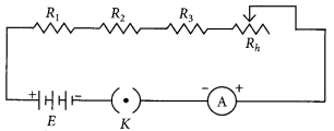 Change the positions of ammeter and note the reading of ammeter each time. You will find that all the reading obtained are same.
So, the value of the current in the ammeter is the same, independent of its position in the electric circuit. It means that in this circuit (series combination) the current is the same in every part of the circuit
Precautions:
(i) All the connections are neat and tight
(ii) Ammeter is connected with the proper polarity, i.e., positive terminal of the ammeter should go to positive terminal and negative terminal of ammeter to the negative terminal of the battery or cell used
Electricity Short Question & Answer:
Question 1.
What is electric current? Define its unit.
Answer:
Electric current is the rate of flow of electric charge through a conductor. It is measured as the amount of charge passing through a conductor in a unit time.
Formula:
I - Q/t
where I is the current, Q is the charge, and t is the time.
The SI unit of electric current is the ampere (A).
1 ampere = 1 coulomb/second.
Question 2.
Define Ohm’s law. Write its mathematical expression.
Answer:
Ohm’s law states that the electric current flowing through a conductor is directly proportional to the potential difference across its ends, provided the temperature and other physical conditions remain constant.
Mathematical expression: V - IR
where V is the potential difference, I is the current, and R is the resistance.
Question 3.
What is the resistivity of a material? Write its SI unit.
Answer:
Resistivity (ρ) is a property of a material that quantifies how strongly it opposes the flow of electric current. It depends on the nature of the material and temperature but not on its dimensions.
SI unit of resistivity is ohm meter (Ωm).
Question 4.
Derive the formula for the equivalent resistance of two resistors connected in series.
Answer:
In a series connection, the total or equivalent resistance Rs is the sum of the individual resistances R1, R2, and so on
Formula:Rs -R1+R2+.....
Question 5.
Derive the formula for the equivalent resistance of two resistors connected in parallel.
Answer:
In a parallel connection, the reciprocal of the equivalent resistance Rp is the sum of the reciprocals of the individual resistances.
Formula: 1/Rp - 1/R1 + 1/R2+.....
For two resistors:
Rp - R1.R2/R1+R2
Question 6.
What is electrical power? Write its formula and unit.
Answer:
Electrical power is the rate at which electrical energy is consumed or produced by a device.
Formula:
P - VI
where P is power, V is voltage, and I is current.
Using Ohm’s law (V - IR), the power can also be written as:
P - I² R or P - V²/R
The SI unit of power is watt (W).
Question 7.
State Joule’s law of heating.
Answer:
Joule’s law of heating states that the heat produced in a resistor is directly proportional to:
- 1.The square of the current (I²)
- 2.The resistance of the conductor(R)
- 3.The time for which the current flows(t)
Formula:H=I² Rt
Question 8.
What is the difference between a series and a parallel circuit?
Answer:
| Series Circuit |
Parallel Circuit |
| The current through each component is the same. |
The voltage across each component is the same. |
| If one component fails, the entire circuit breaks. |
If one component fails, the others continue working. |
| Total resistance is the sum of individual resistances. |
Reciprocal of total resistance is the sum of the reciprocals of individual resistances. |
Question 9.
How is electrical energy measured in households?
Answer:
Electrical energy is measured in kilowatt-hours (kWh) in households, which is the amount of energy consumed by a 1 kW appliance running for 1 hour.
1 kWh = 1000 watt × 1 hour = 3.6 × 10^6 joules.